Site under construction — check back daily for updates
Research Project
Material Feedback in
Robotic Steam
Bending
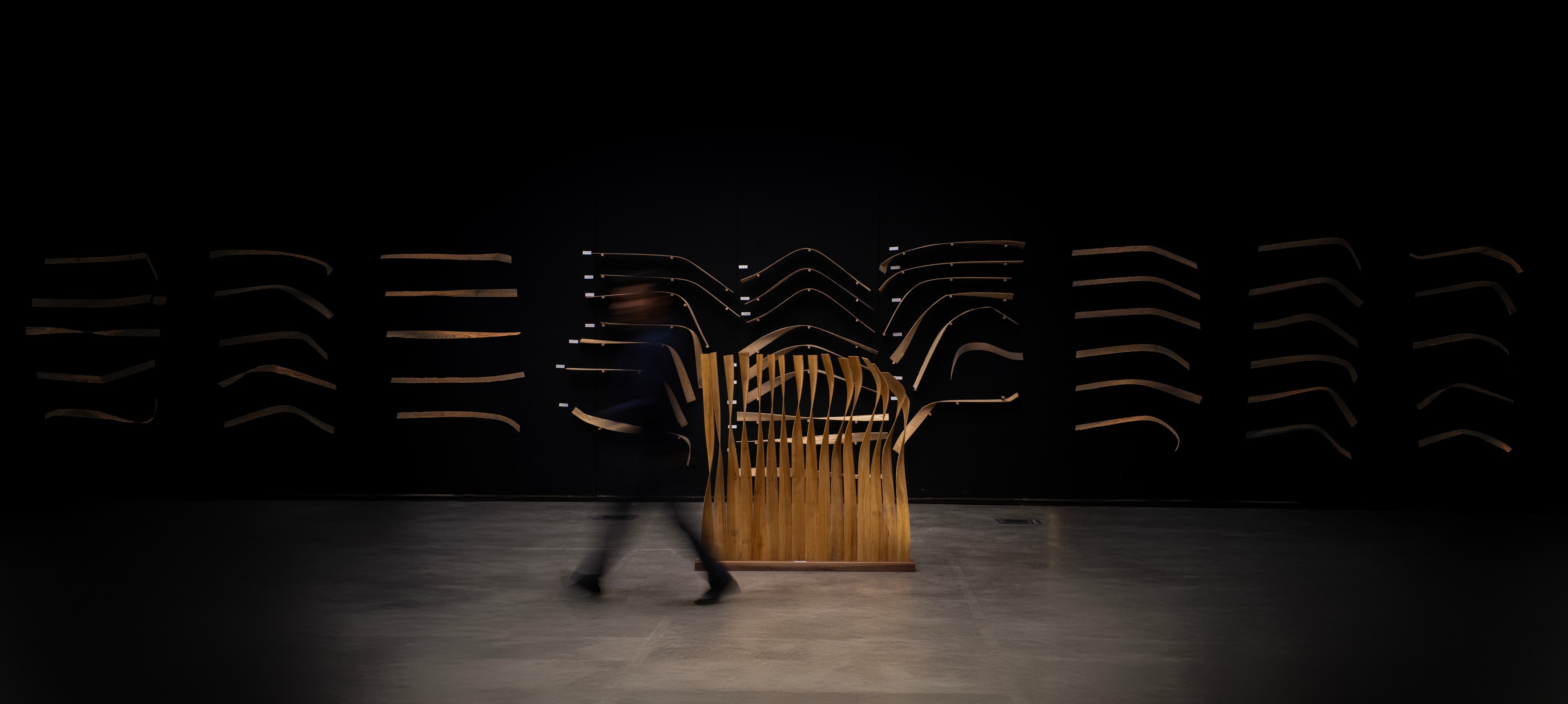
A quantitative approach to formwork-free robotic steam bending through computational path planning, sensing, re-digitization, and material feedback.
Olivia Carson,Liam Cassano,Karina Craig,Micha Fairfax-Angood,Nicholas Hoban,Maria Yablonina
Robotics
KUKA KR150
UR10e
Computation
Rhino
Grasshopper
Robot Control
KUKA|prc
Simulation + Optimization
Kangaroo
Galapagos
Sensing + Scanning
HTC Vive Tracker
EinScan Pro 2X
Materials Tested
Ash
White Oak
Red Oak
01
Research Question
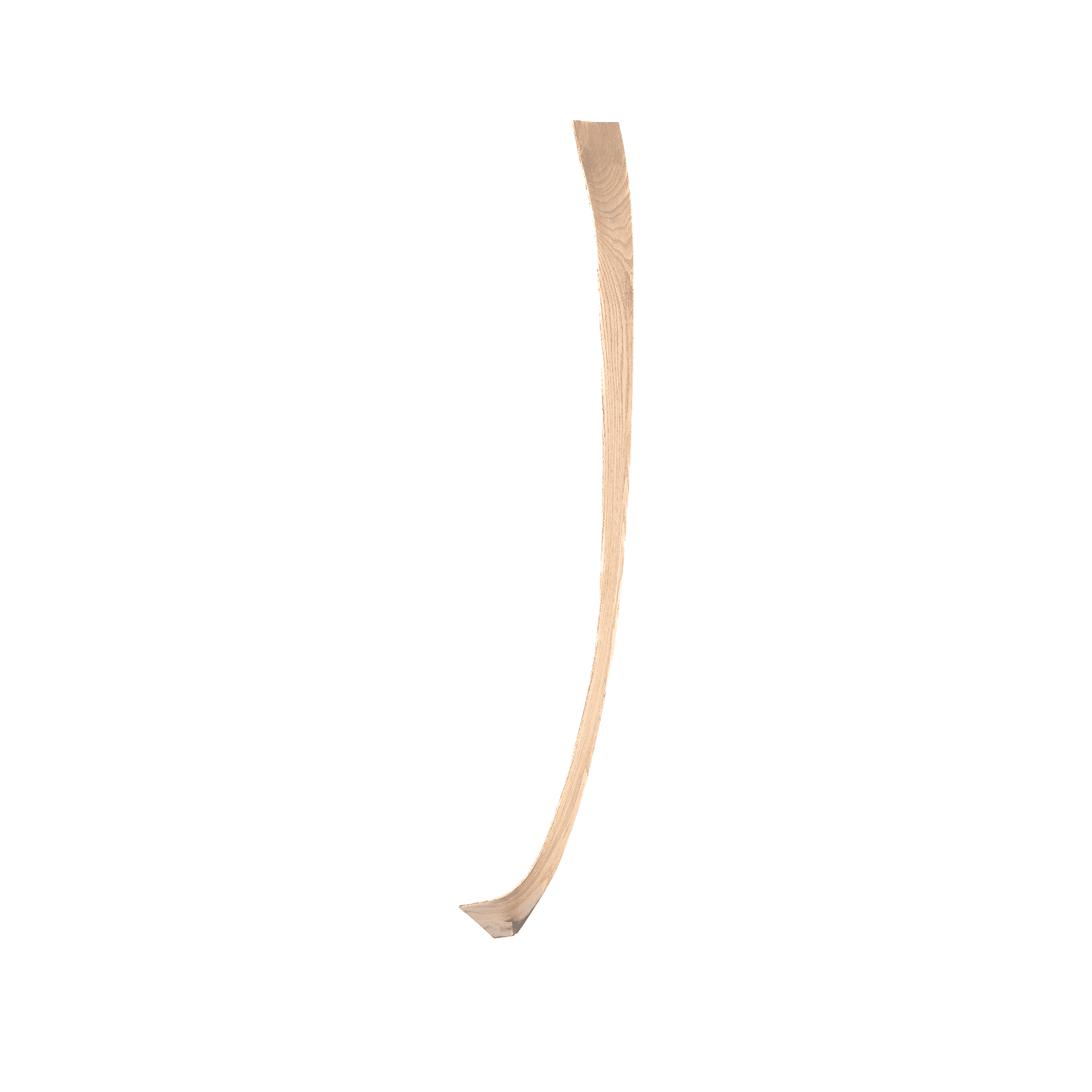
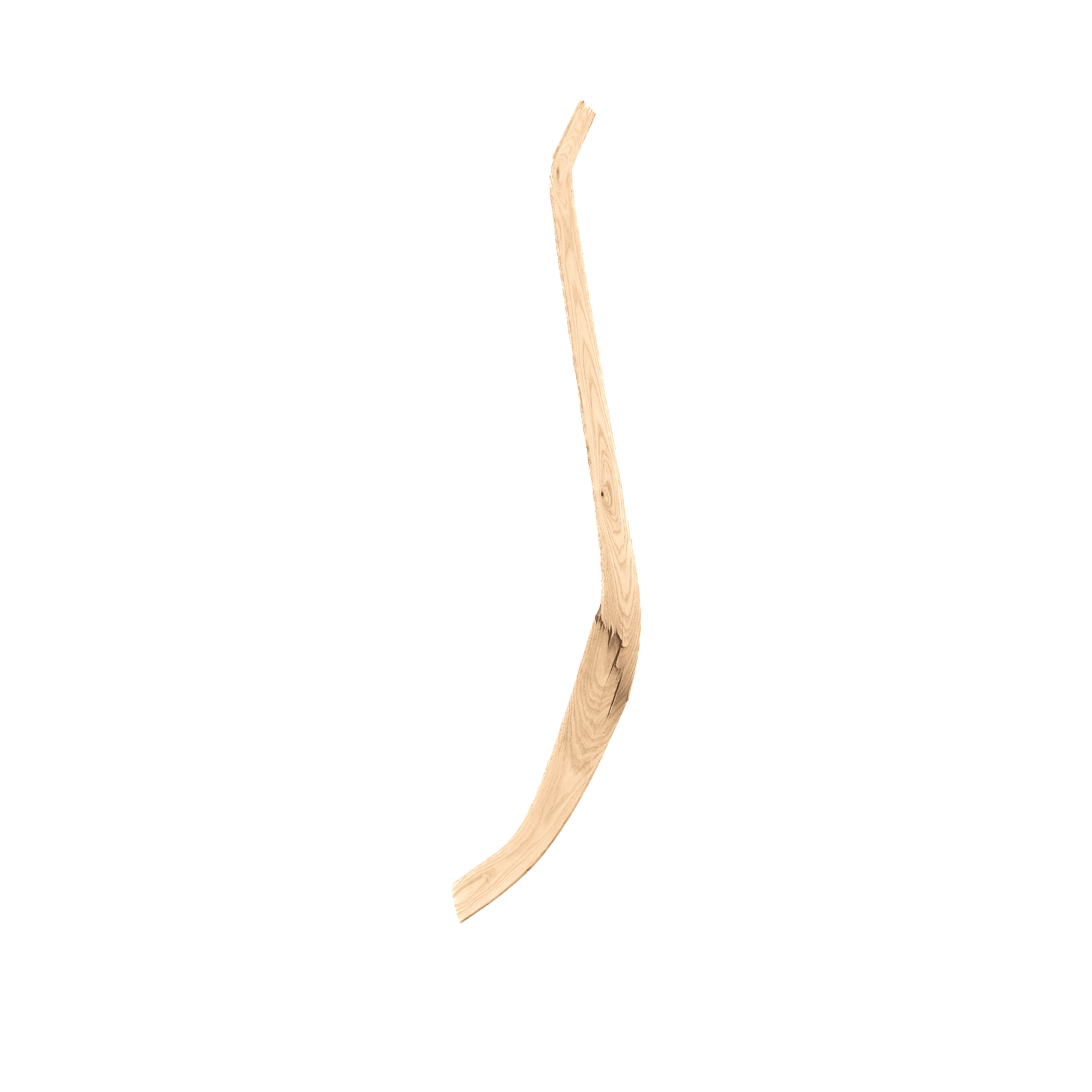
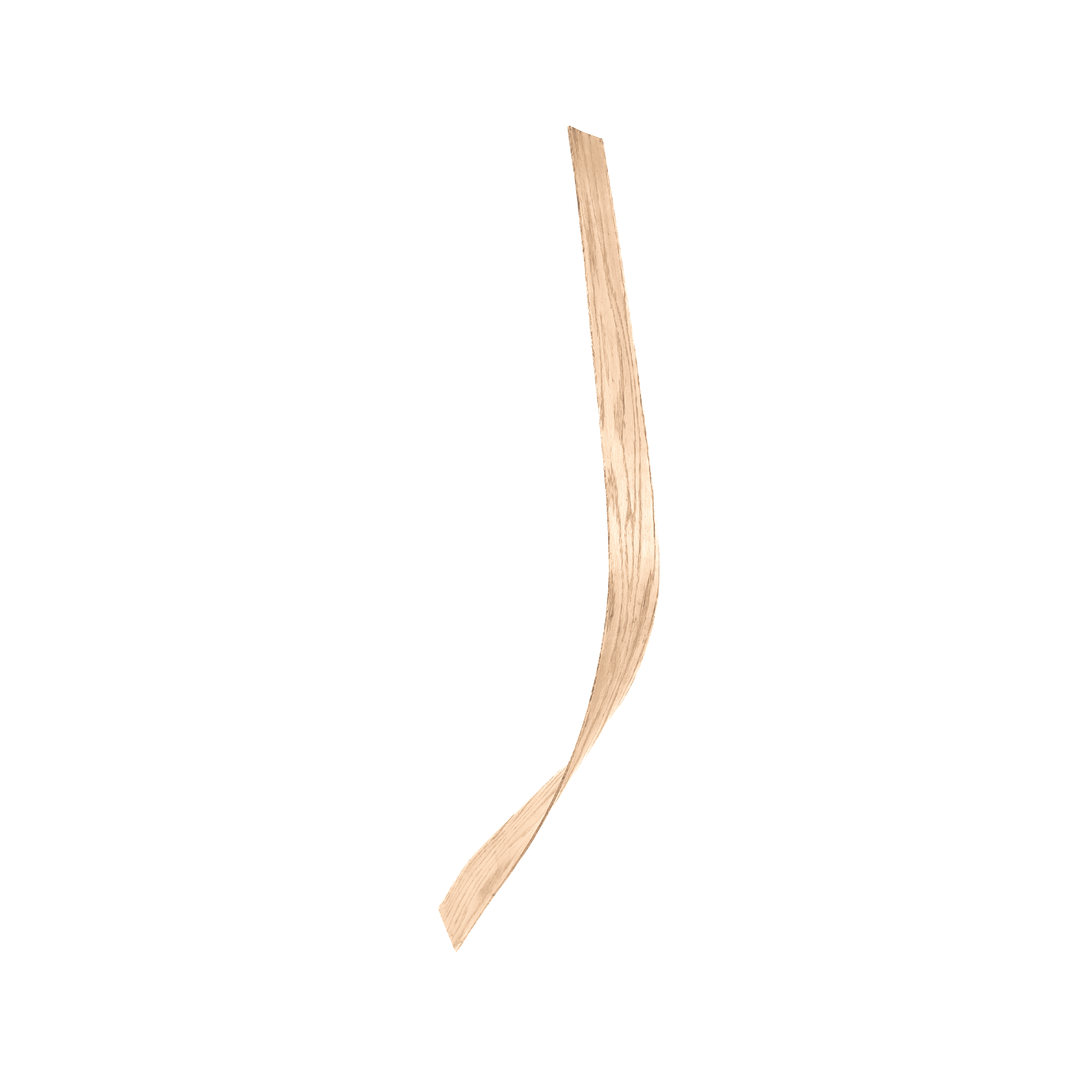
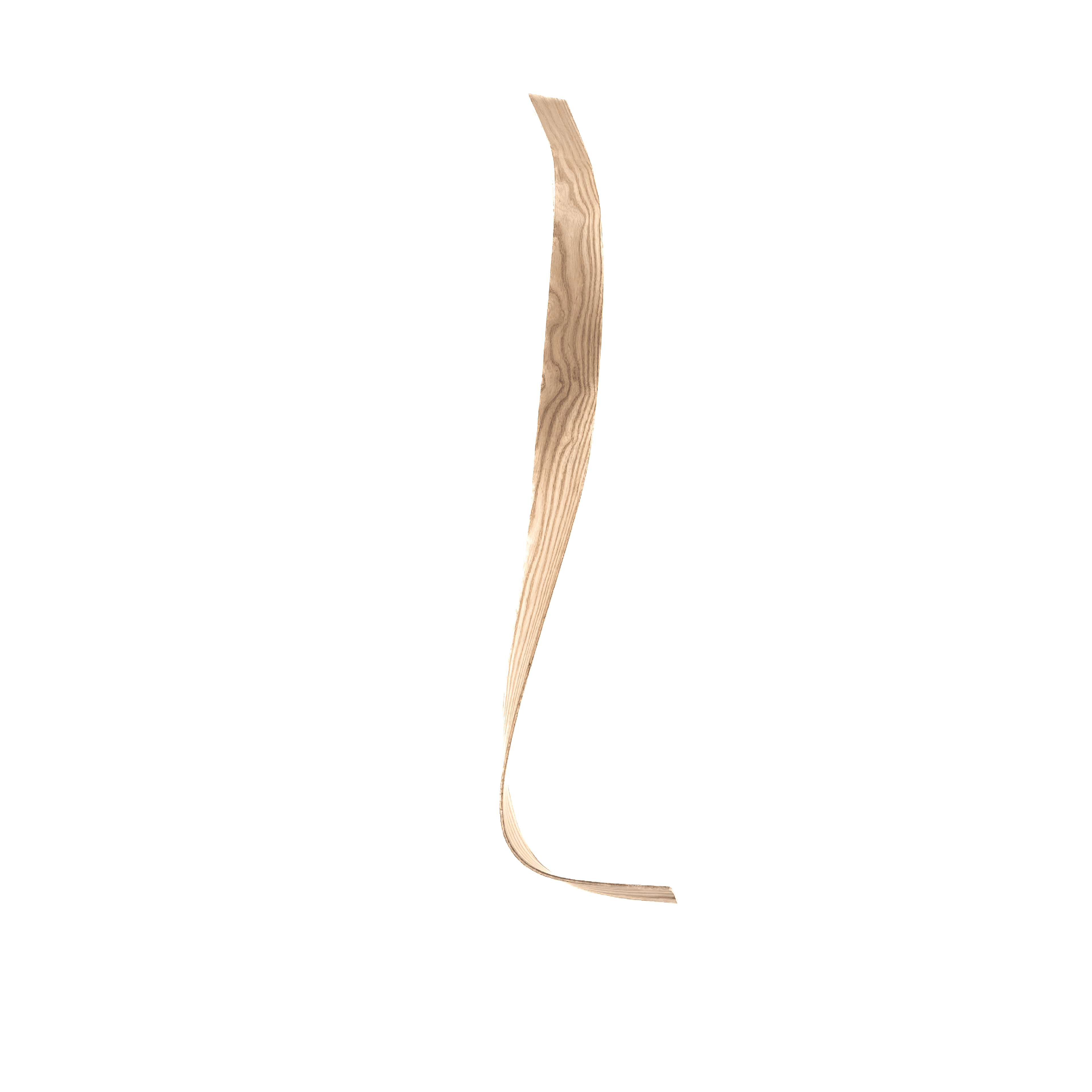
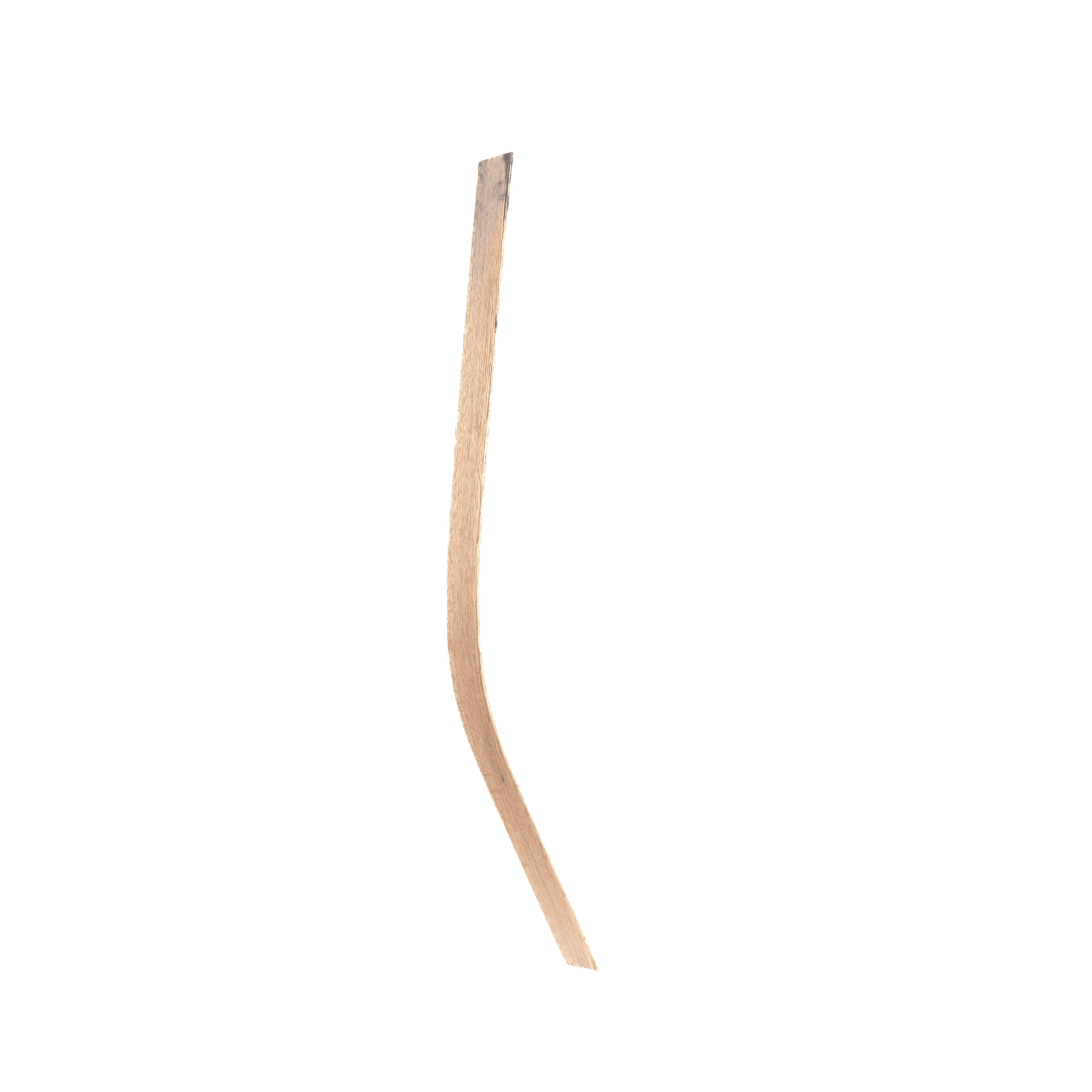
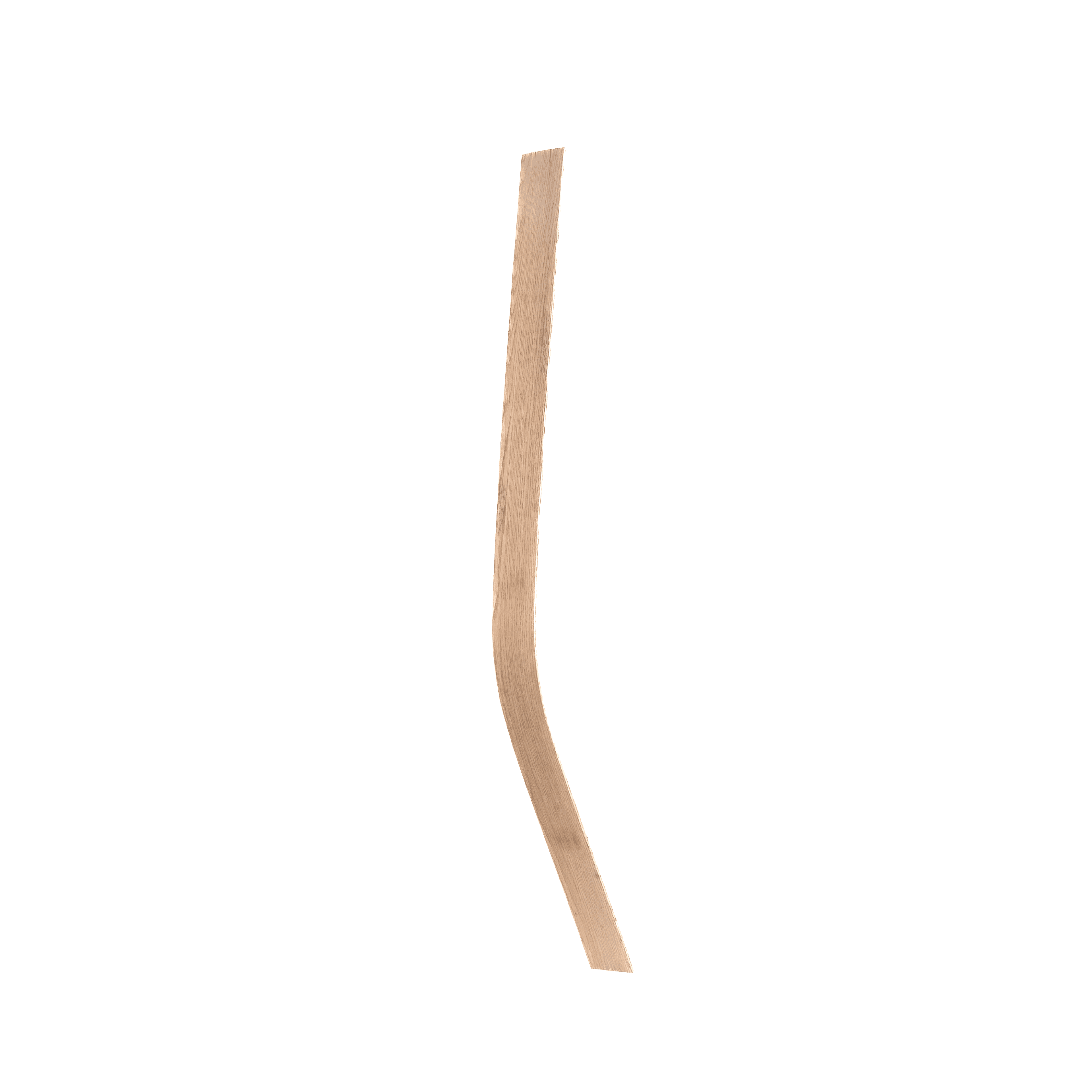
Can computational path planning and empirical material data enable accurate, repeatable, and formwork-free robotic steam bending?
Conventional steam bending typically relies on rigid moulds or formwork to constrain the material during shaping. This works well for repeated components, but becomes inefficient when every member requires a unique curvature.
This research investigates whether robotic control and material feedback can replace fixed formwork with a digitally controlled bending process capable of producing varied geometries.




02
Manual Testing +
Material Selection
Early physical testing established material behaviour, bending limits, and fabrication requirements before transferring the process to robotic control.
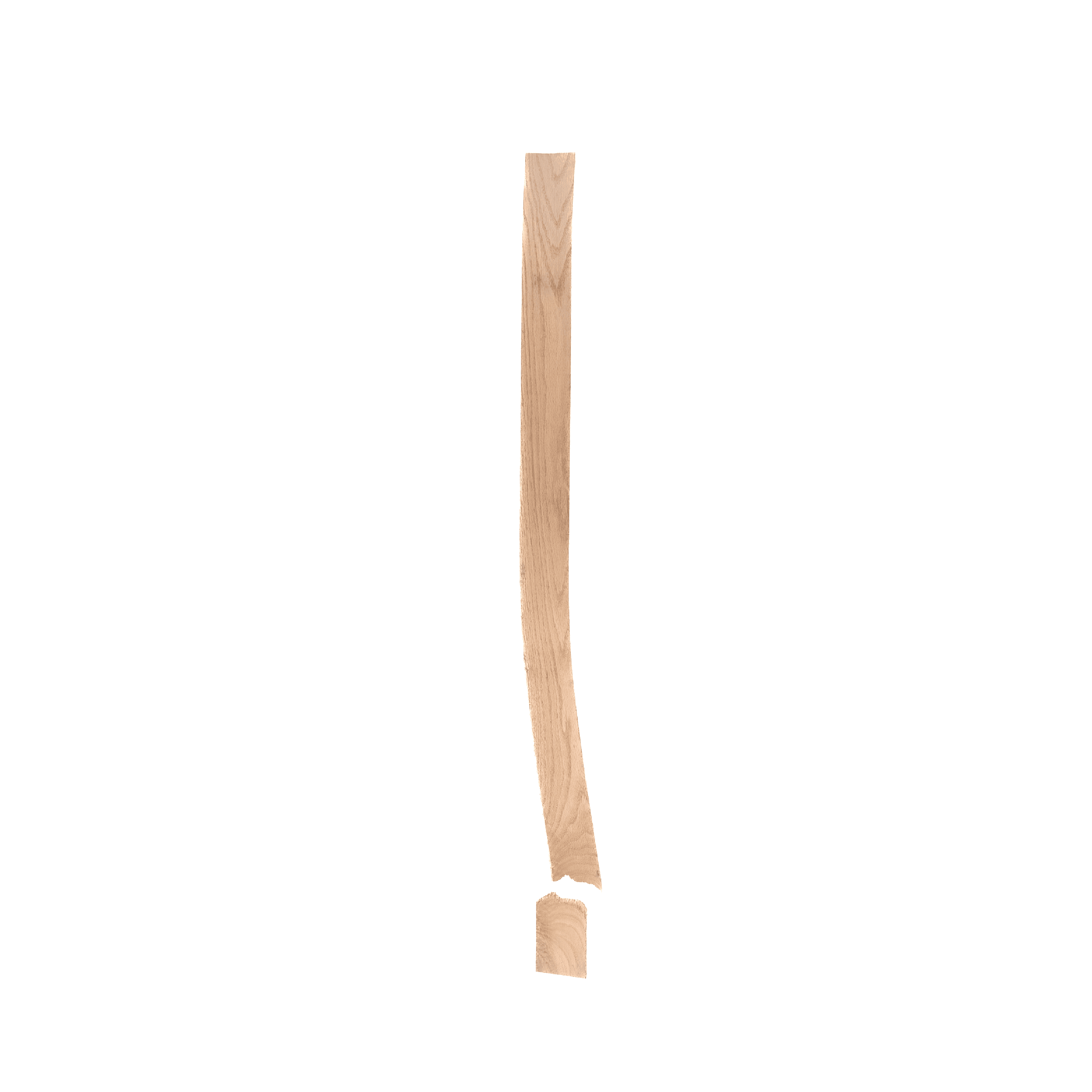
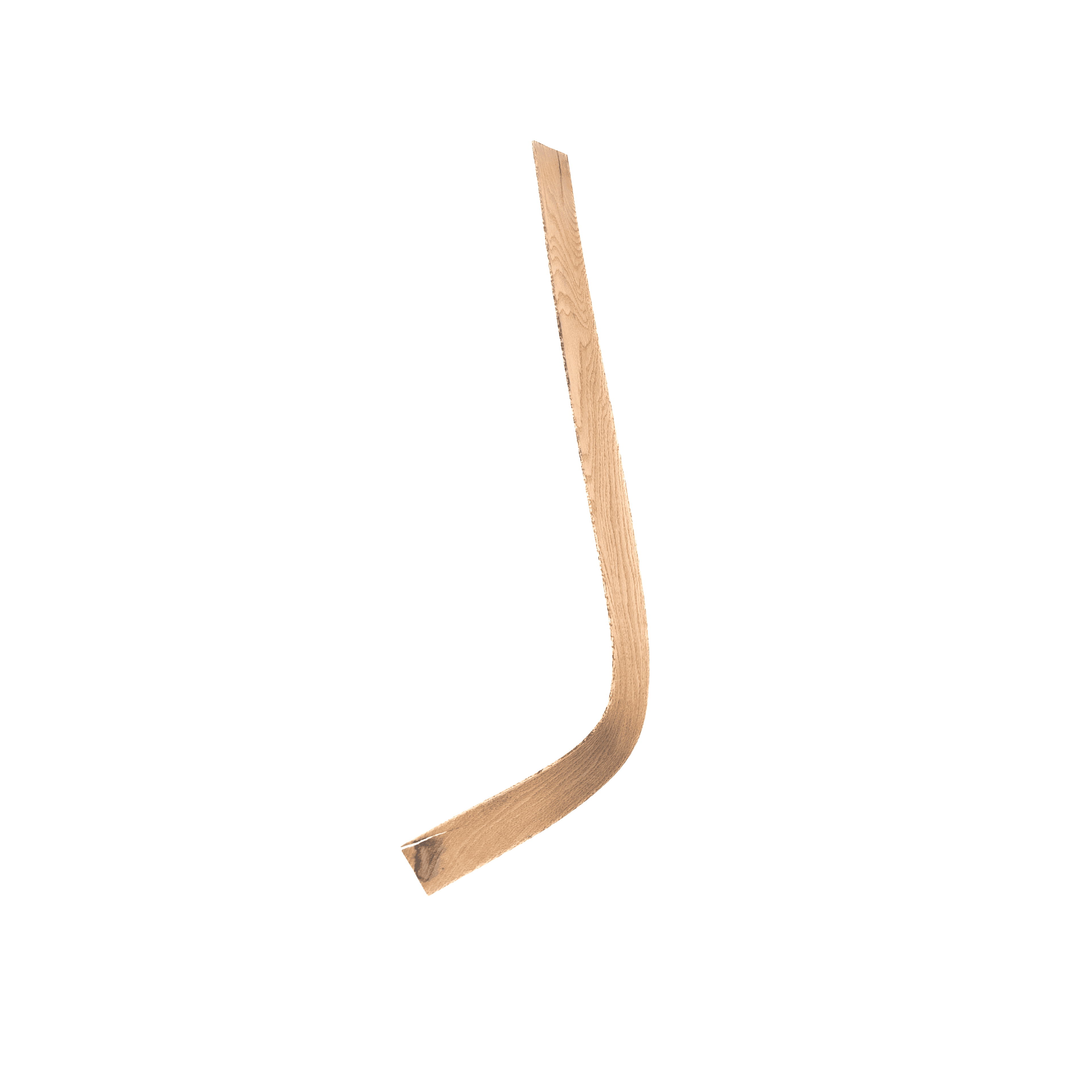
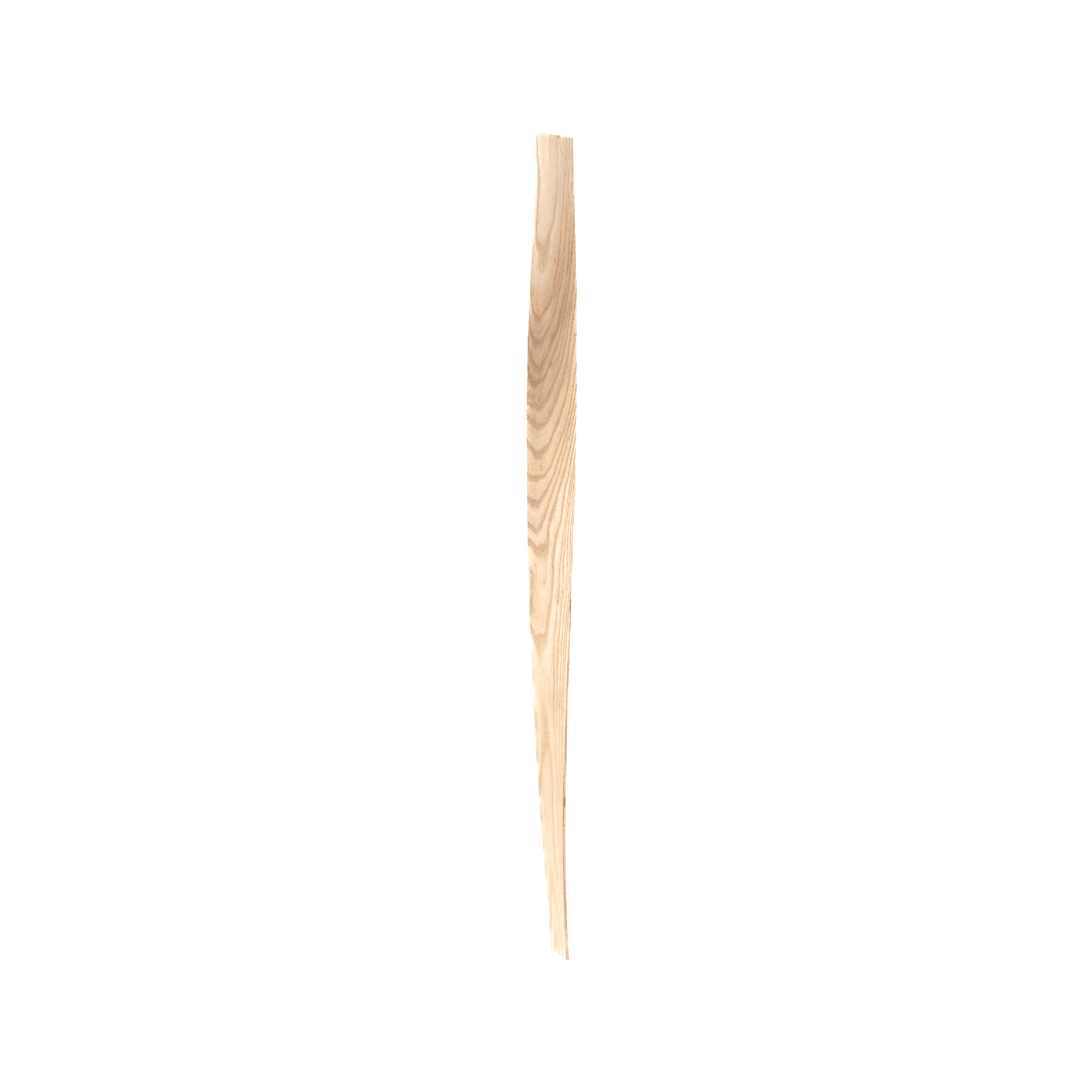
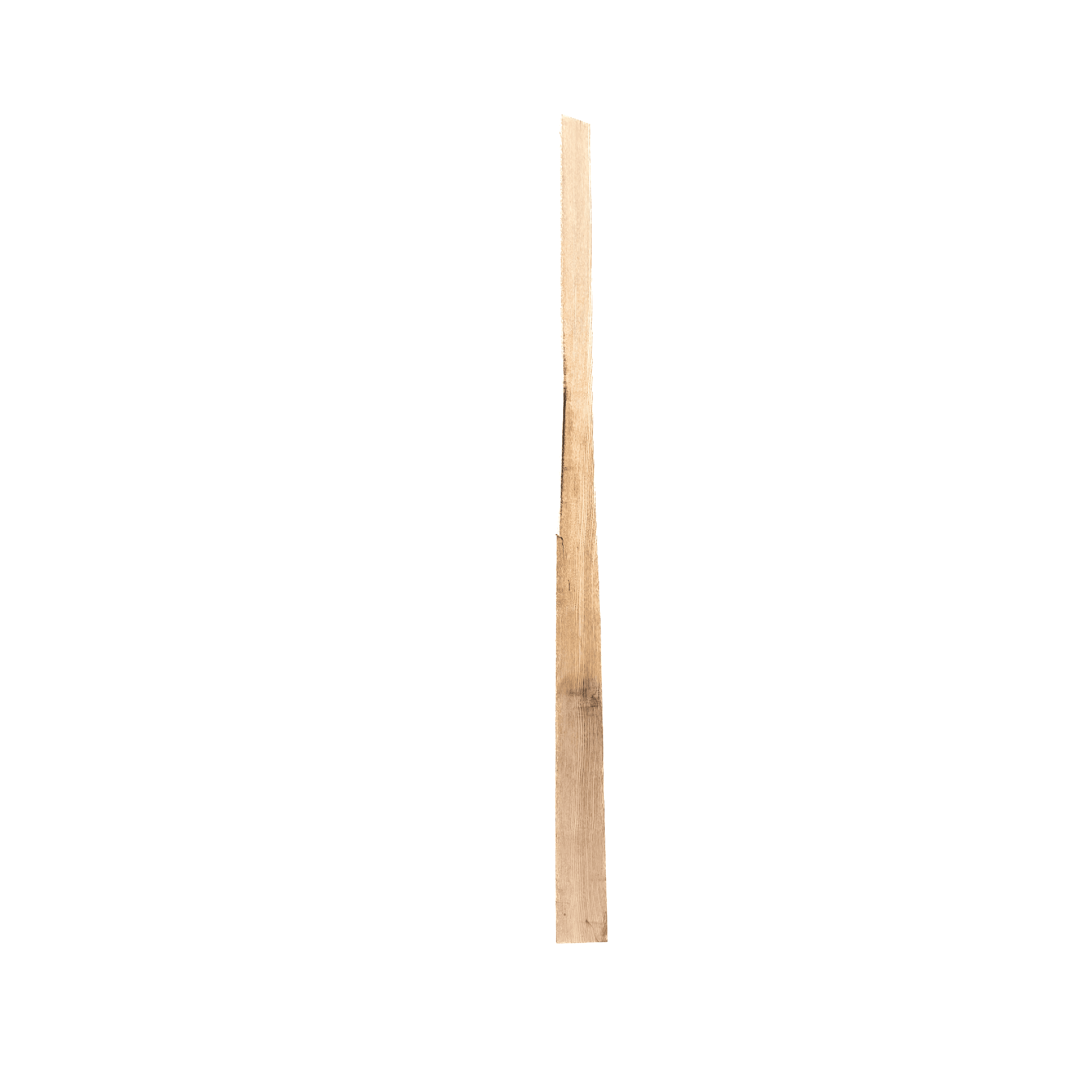
Ash, white oak, and red oak were tested through repeated manual steam-bending experiments. A custom steam chamber was designed and fabricated to prepare the timber under consistent steaming conditions before each bending test. Material behaviour was then compared across the three species to identify suitable stock for robotic testing.
Custom Steam Chamber ↗Rift-sawn stock provided the most reliable bending behaviour. A custom compression strap was introduced to constrain the outside face of the timber, reduce tensile failure, and improve consistency as tighter curvatures were produced.
Custom Compression Strap ↗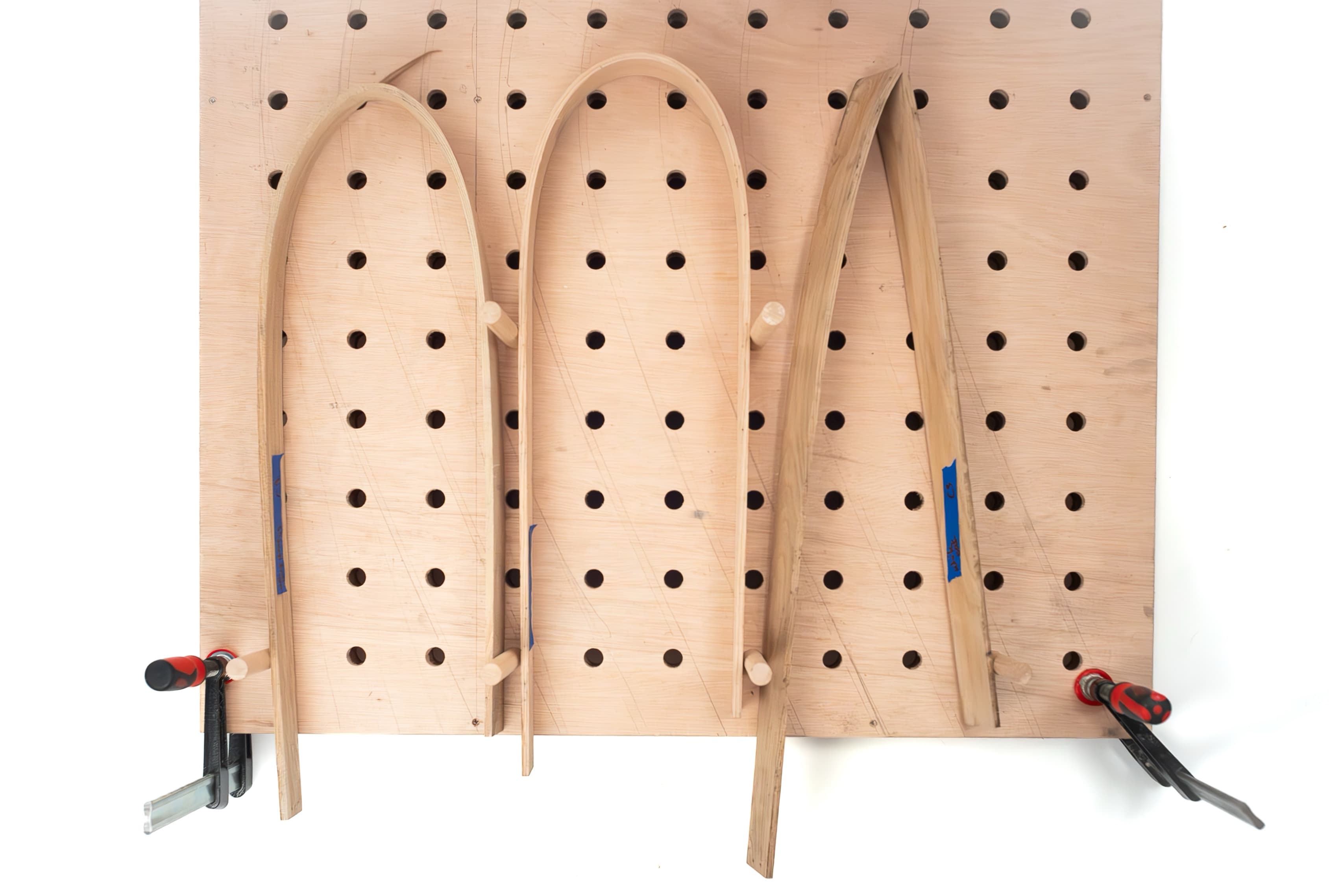
03
Robotic Bending
System
The fabrication workflow distributes bending and drying operations between two robotic systems with distinct roles.
A KUKA KR150 performs the primary bending operation, following computationally generated trajectories developed in Grasshopper and KUKA|prc. Custom tooling constrains and manipulates the timber throughout the forming sequence.
Custom Gripper ↗A UR10e performs a repeatable flash-drying sequence while the member remains constrained, allowing heat application to be controlled consistently before the timber is released.
Custom Heat Tool ↗04
Computational
Path Planning
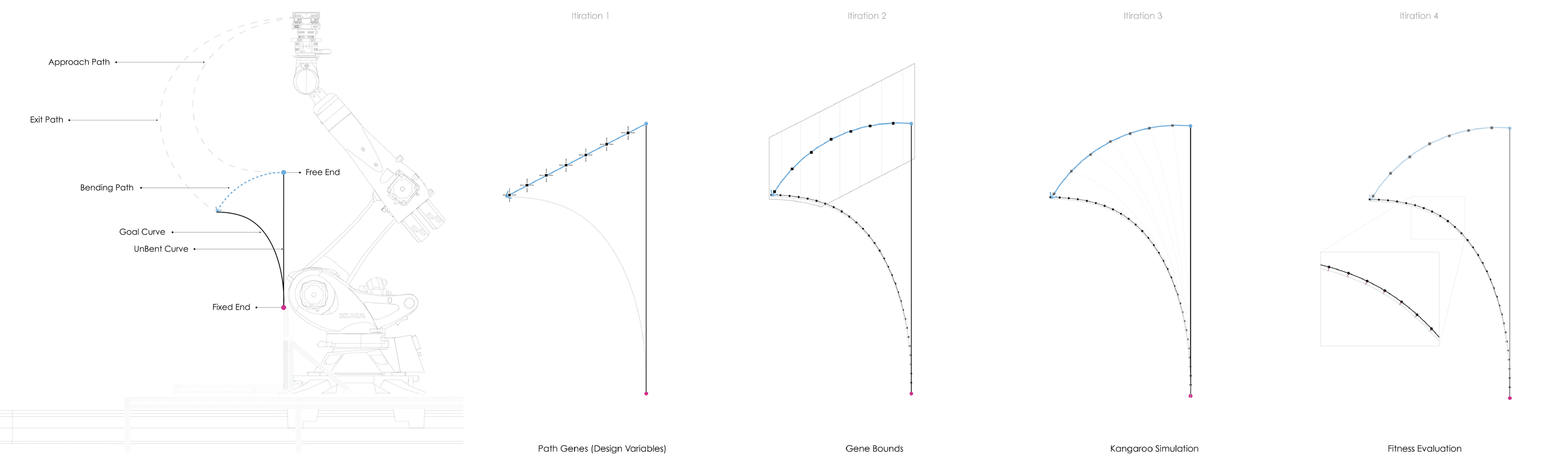
Robot motion is generated from target curvature rather than a fixed mould, using simulation and optimization to develop feasible bending trajectories before fabrication.
Kangaroo dynamic relaxation was used to simulate bending behaviour and evaluate candidate geometries before physical fabrication.
Galapagos provided an optimization framework for iterating design variables and evaluating candidate solutions against the desired bending geometry.
05
Sensing +
Re-Digitization
Physical bending results are re-digitized so material behaviour can be measured and compared against the computational geometry.
An HTC Vive Tracker was used for rapid spatial tracking during the development of the bending workflow, providing a fast method for recording physical position.
Higher-resolution geometry was captured with an EinScan Pro 2X structured-light scanner, allowing fabricated members to be digitally reconstructed for geometric comparison.
HTC Vive Tracker
Structured-light scanning
06
Experiment
Design
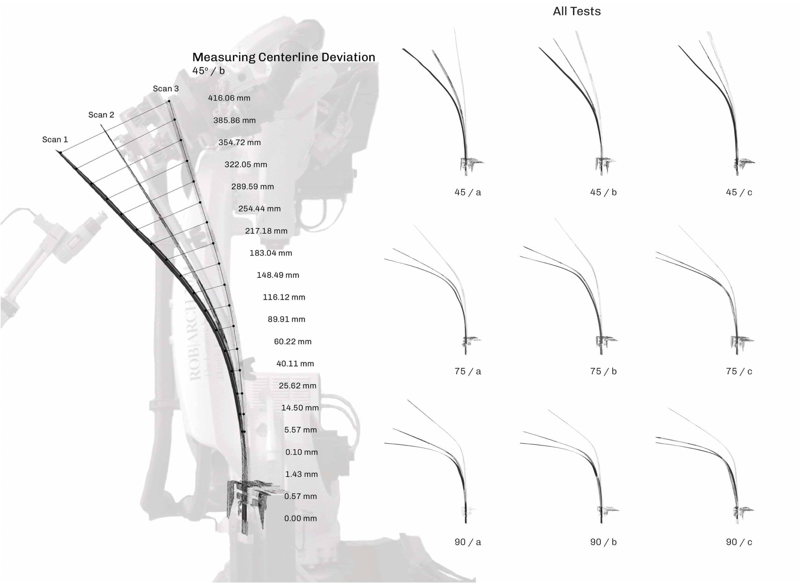
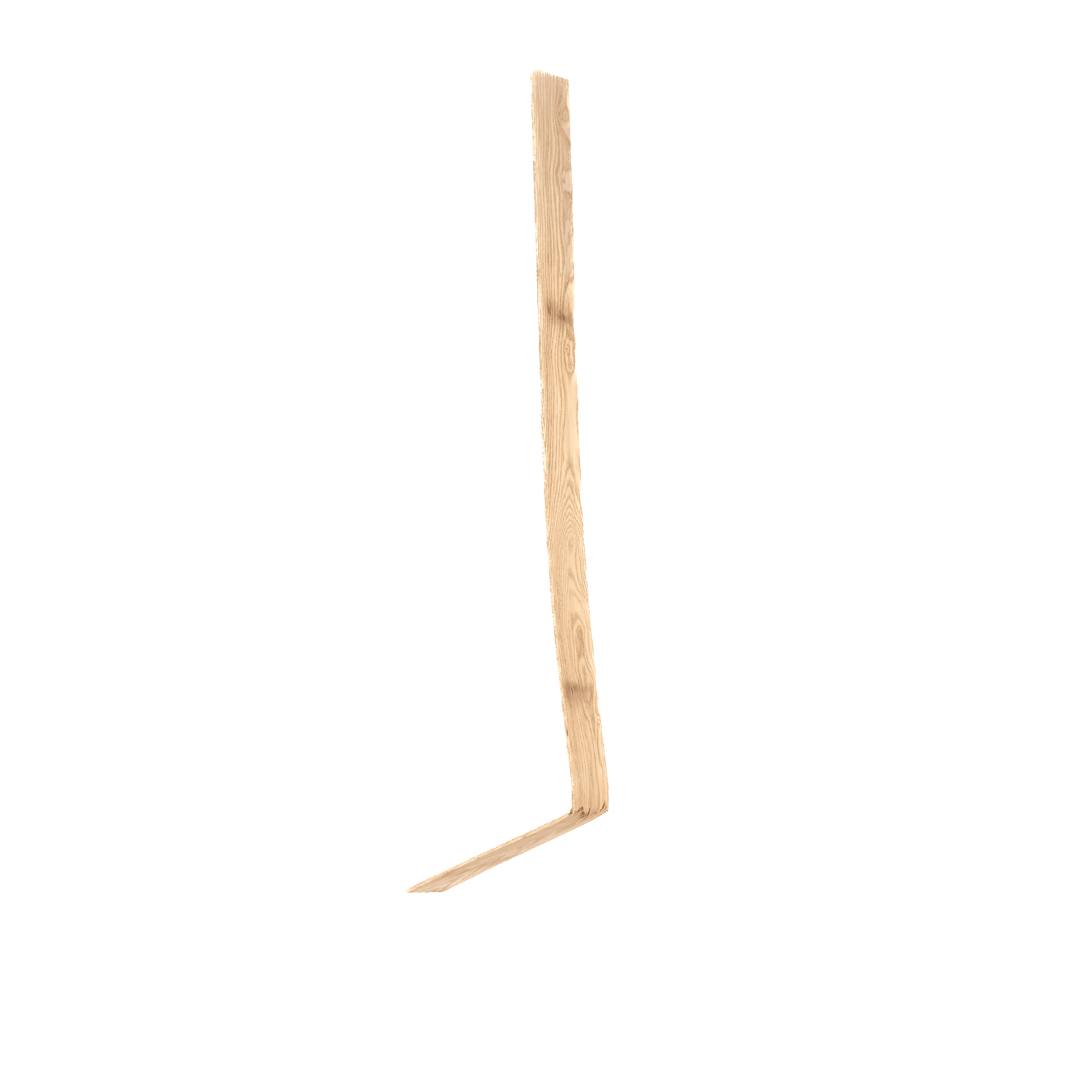
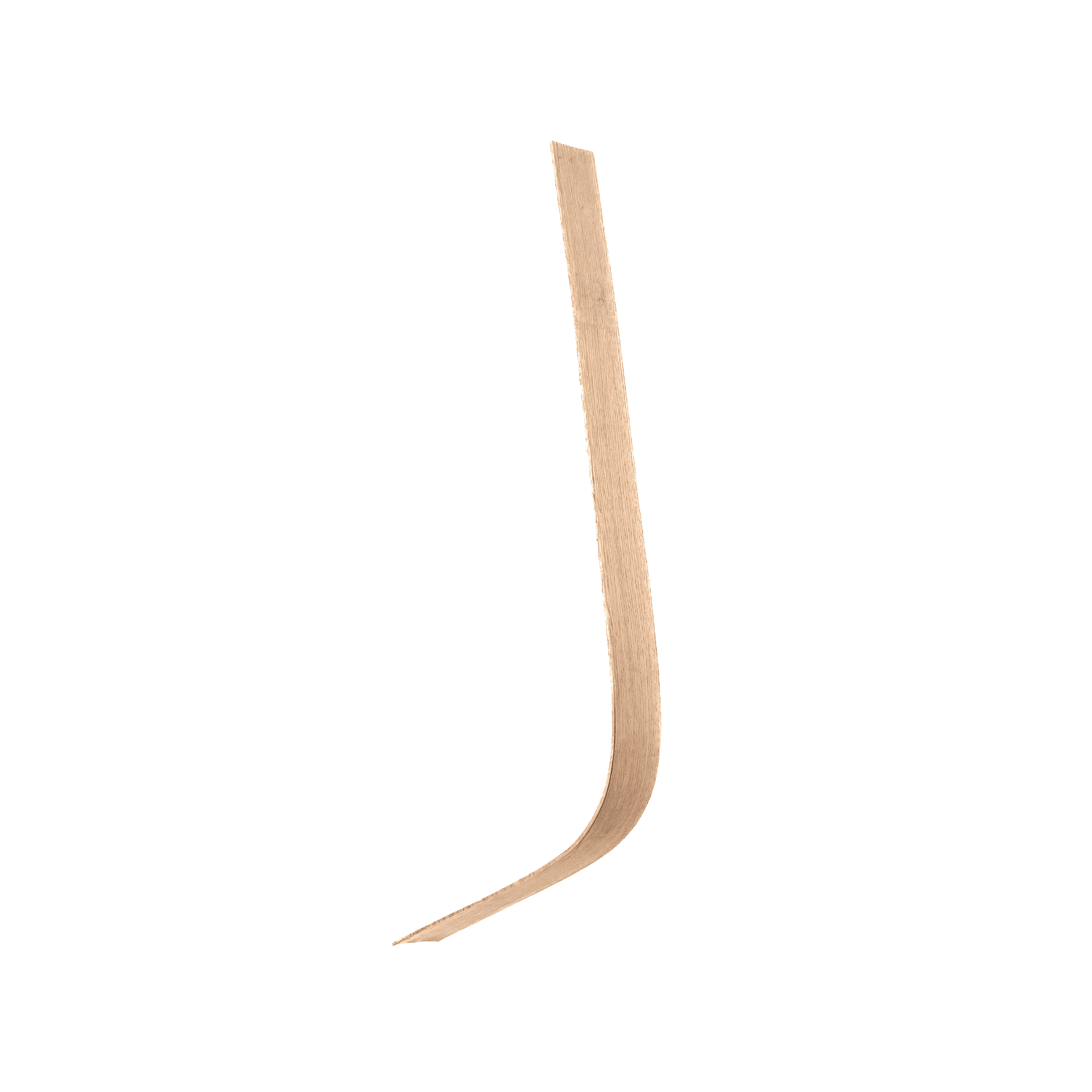
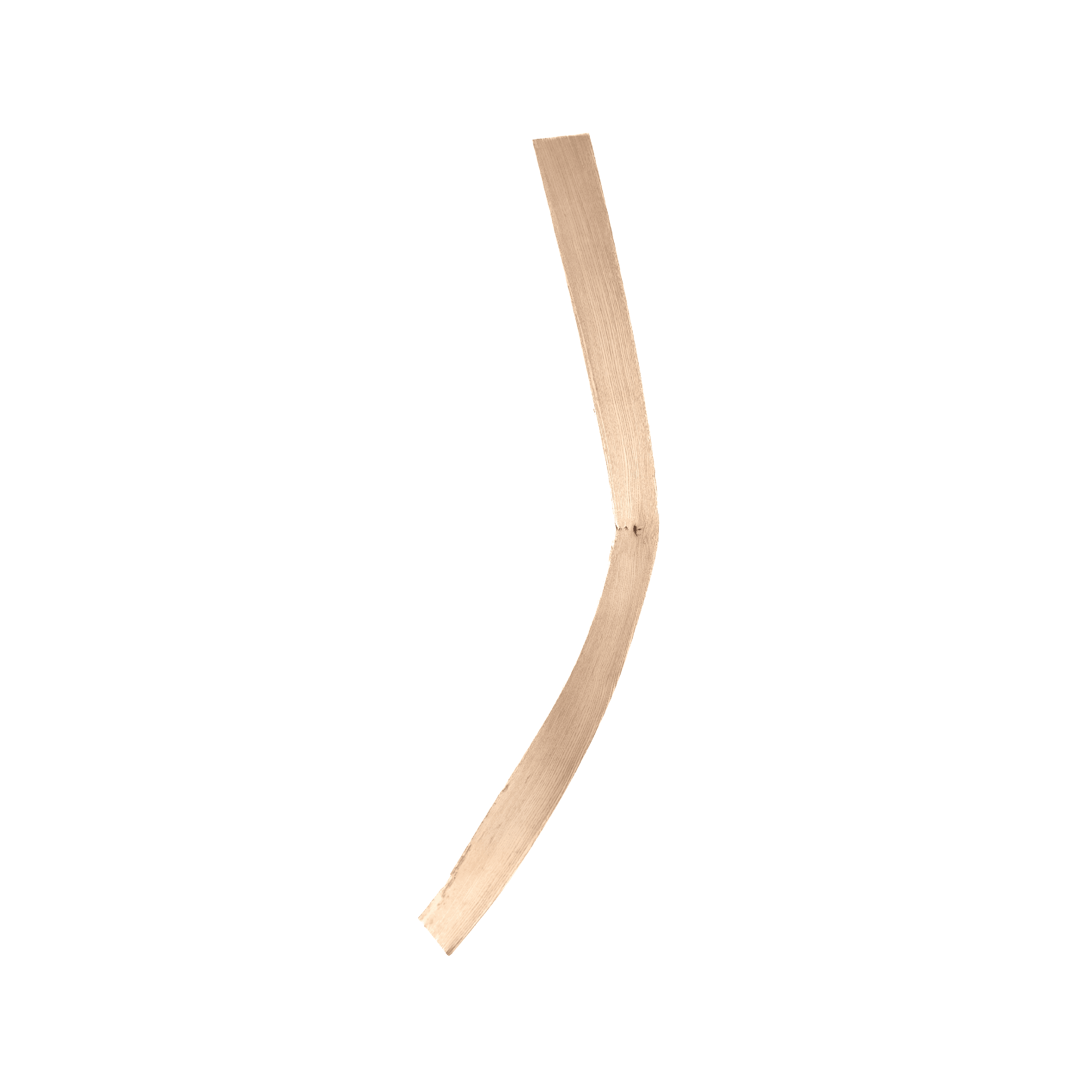
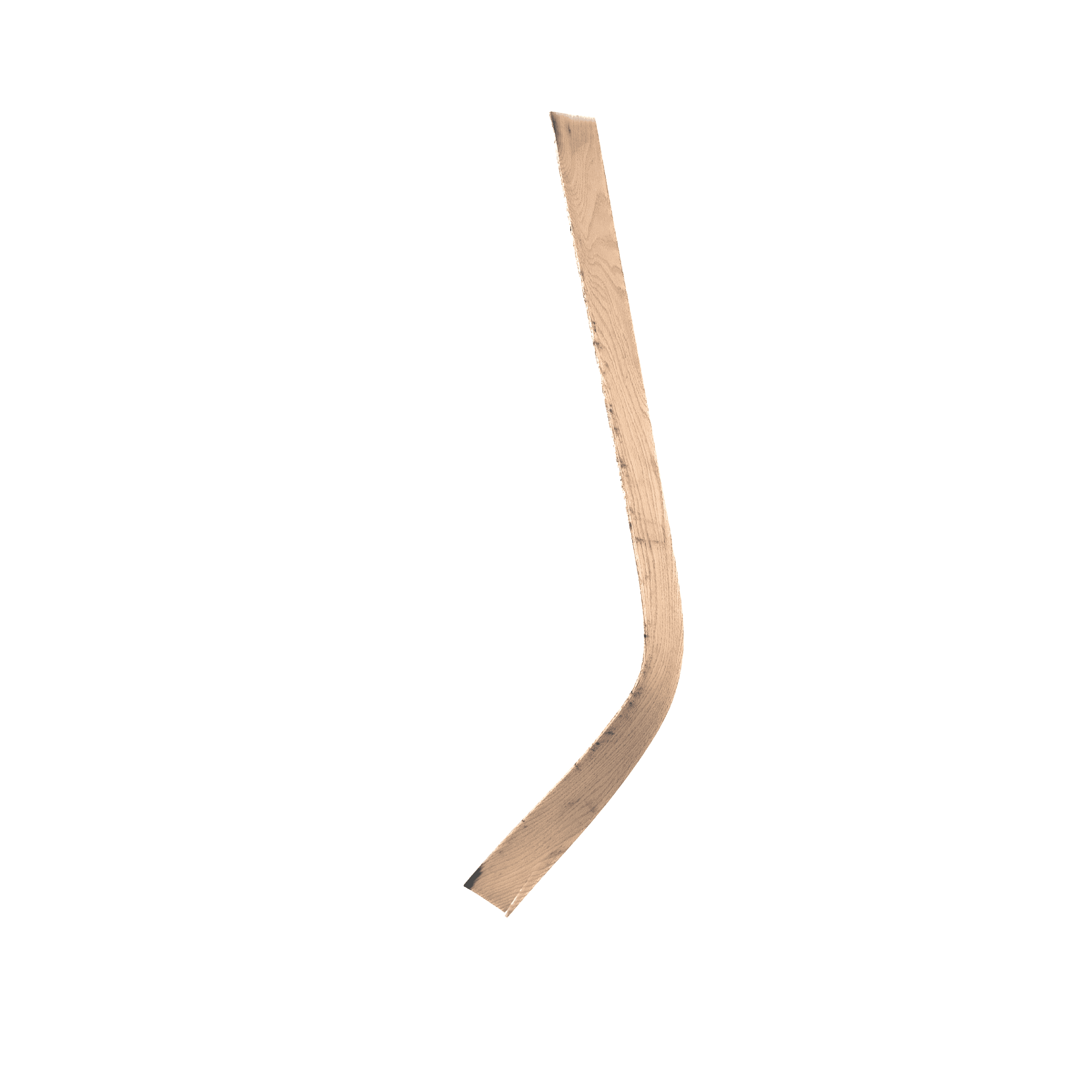
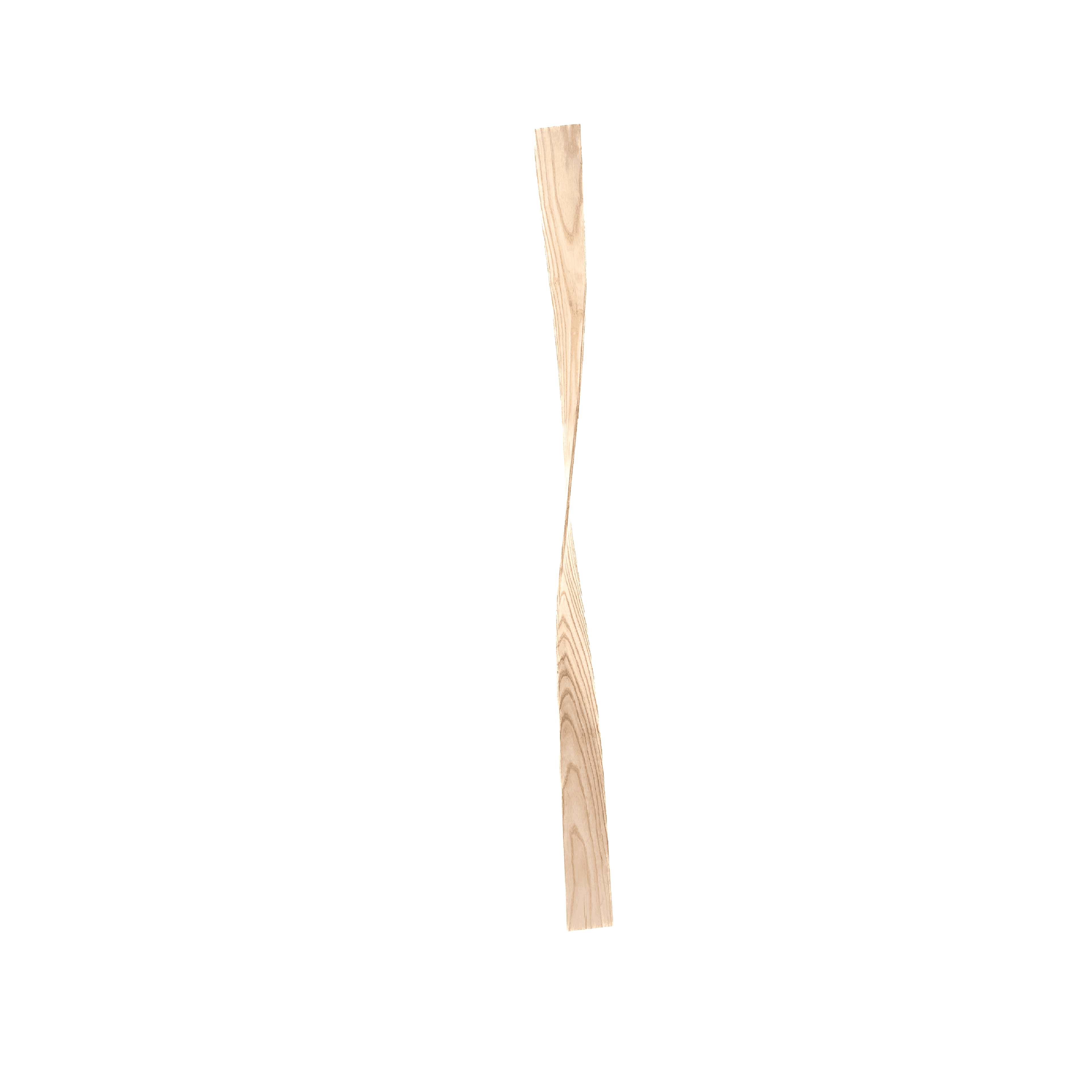
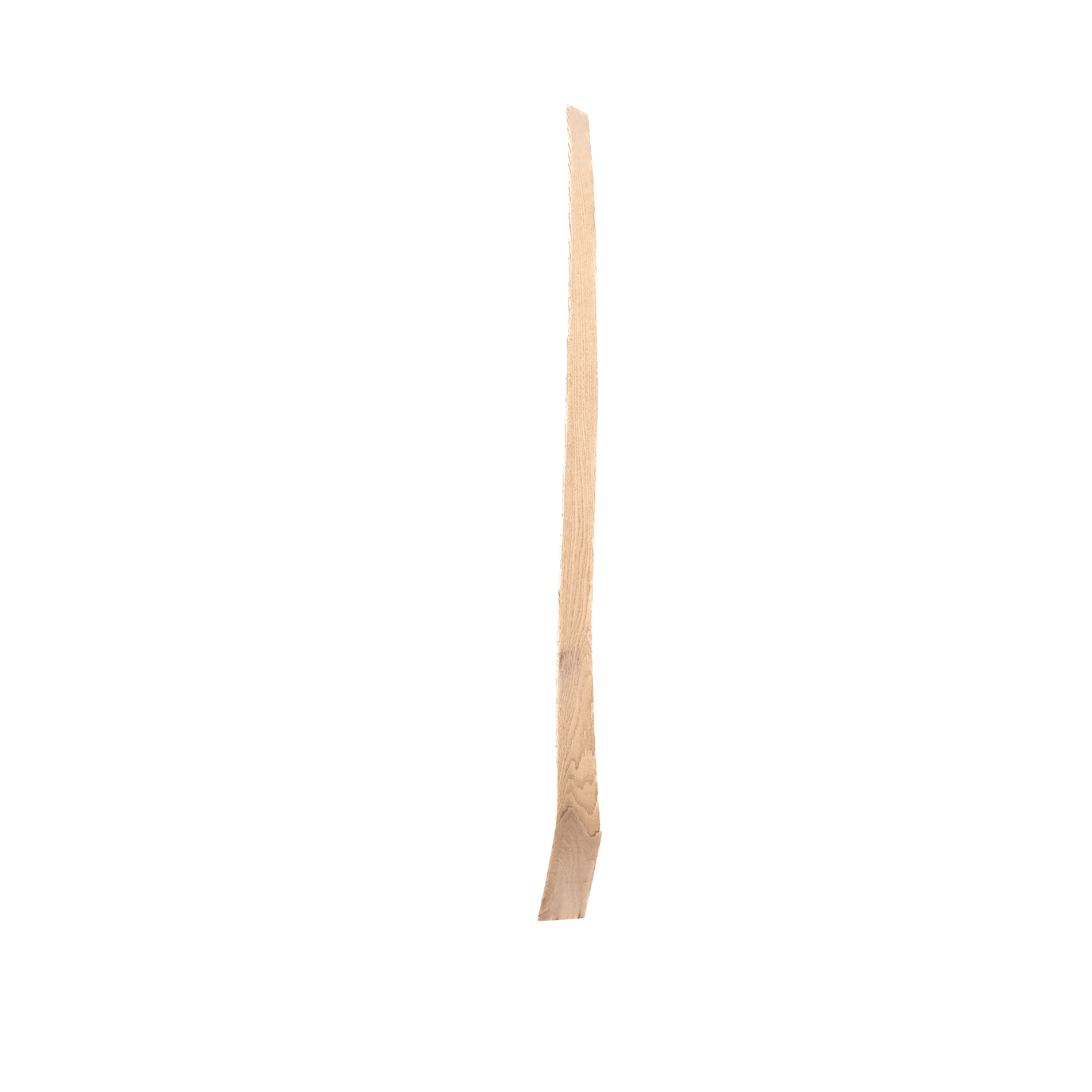
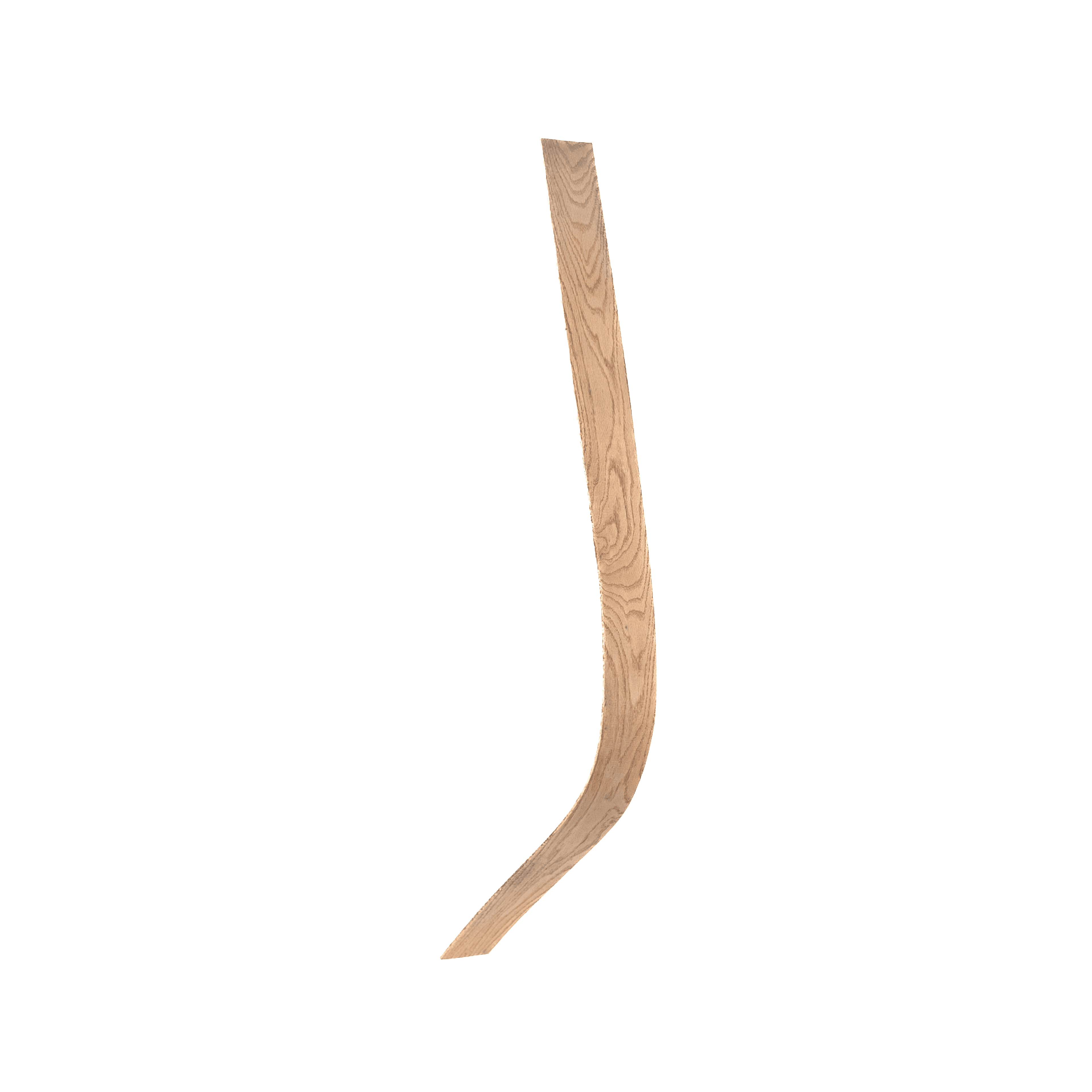
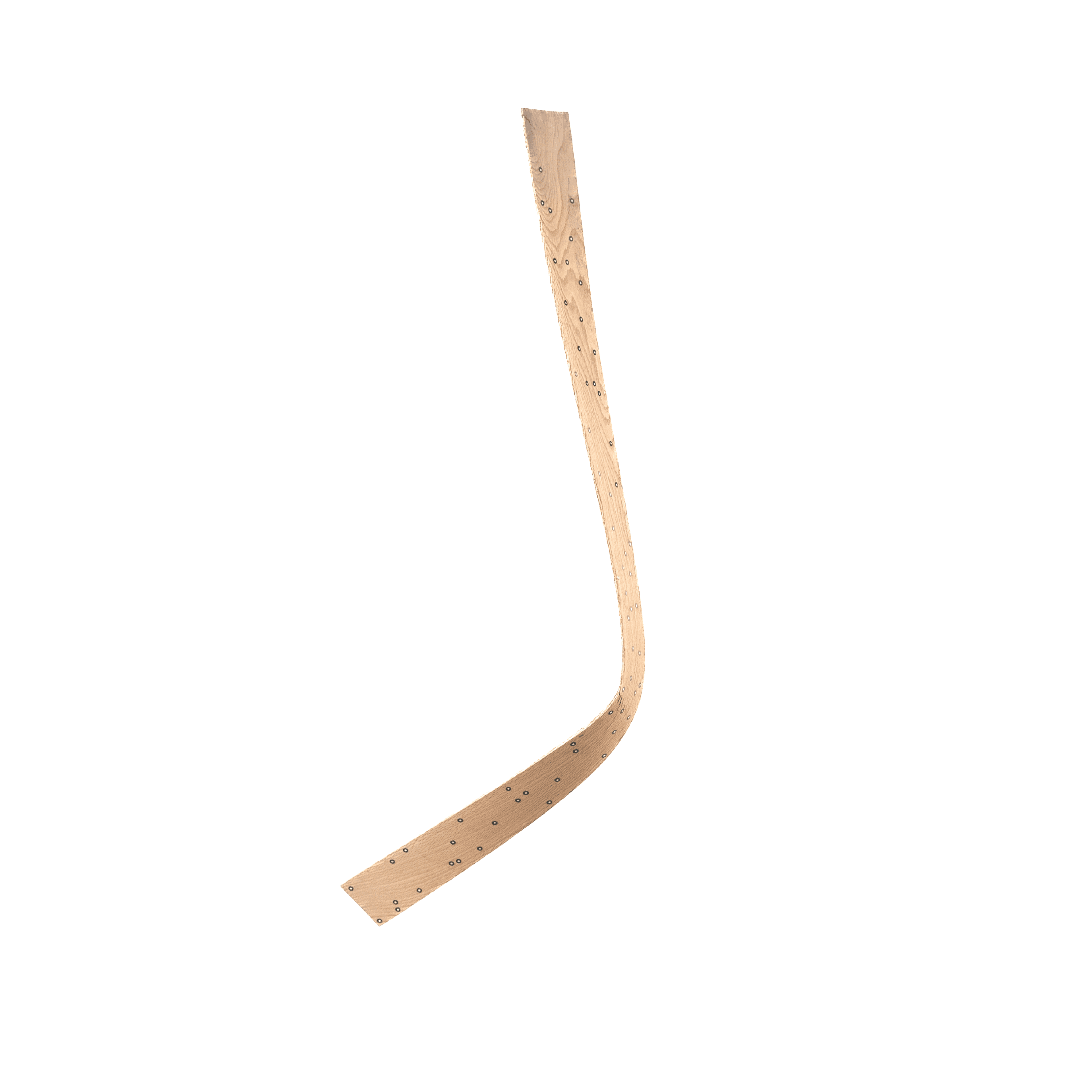
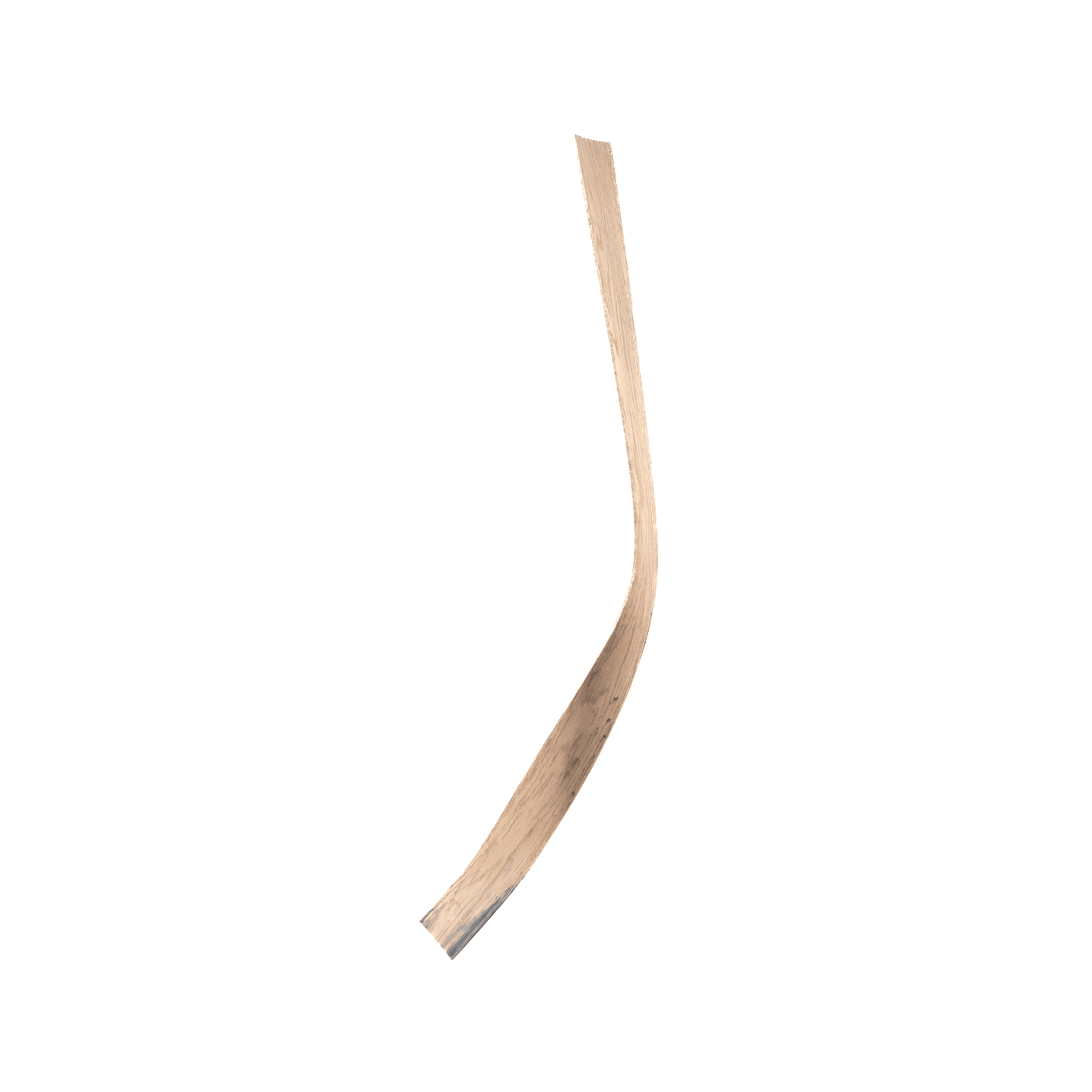
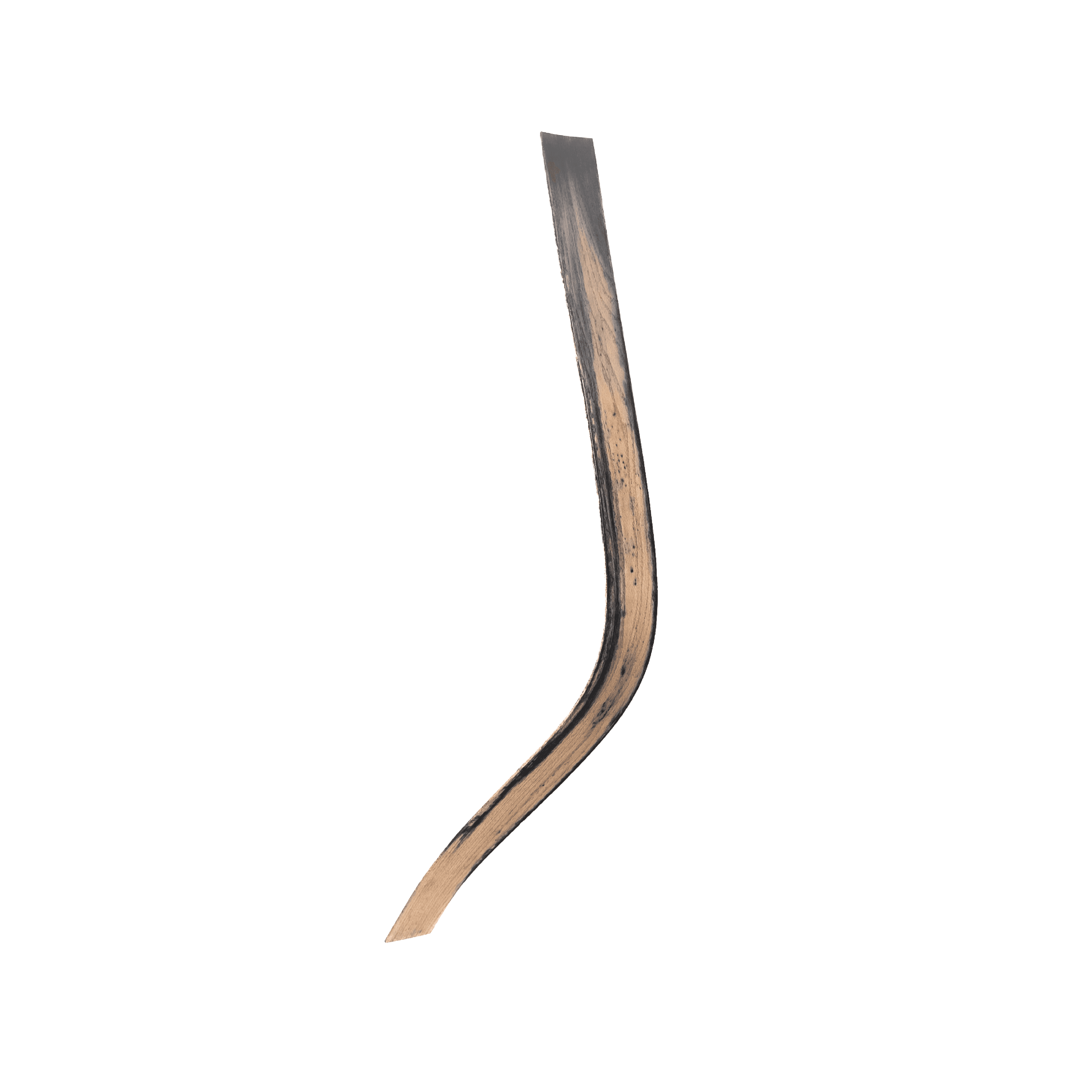
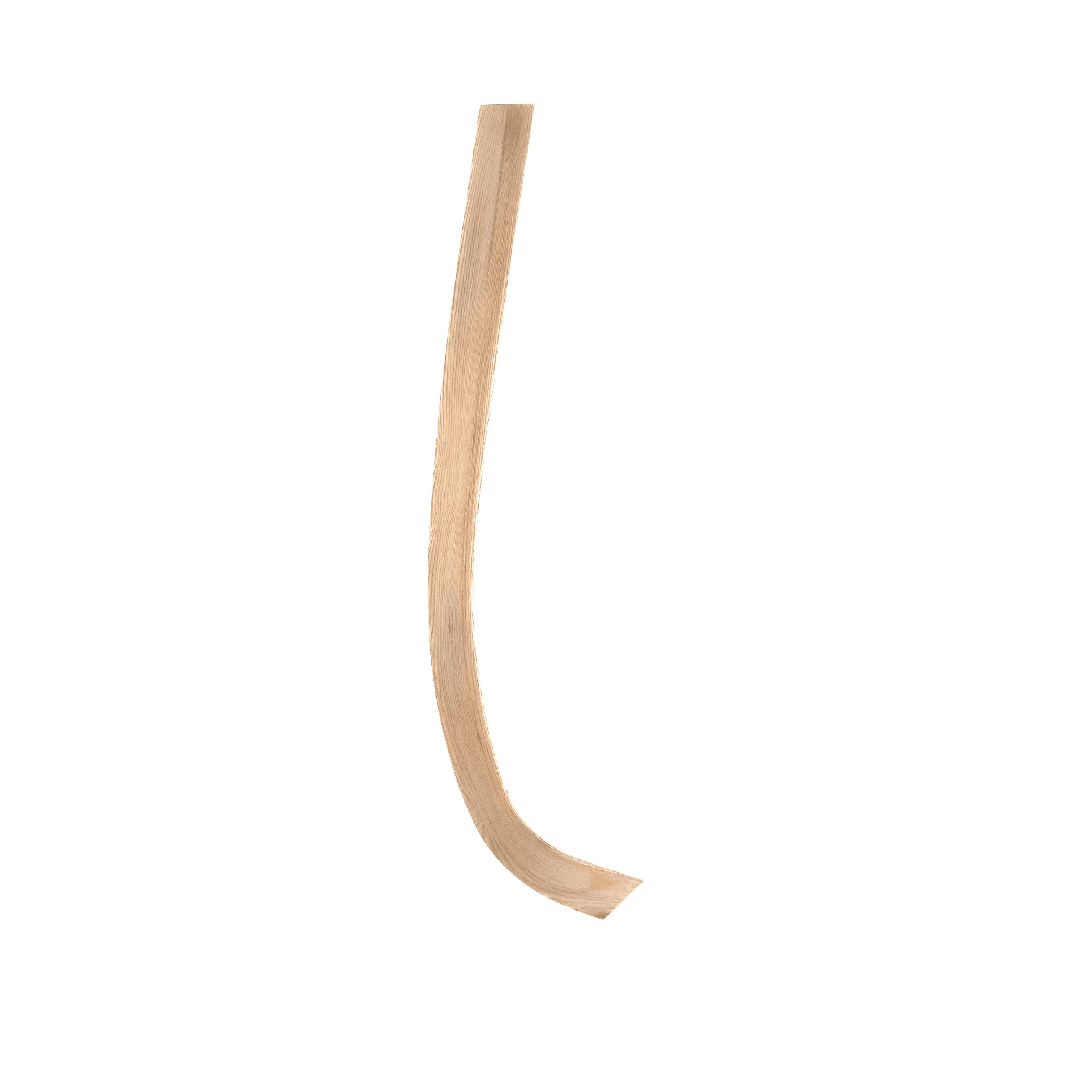
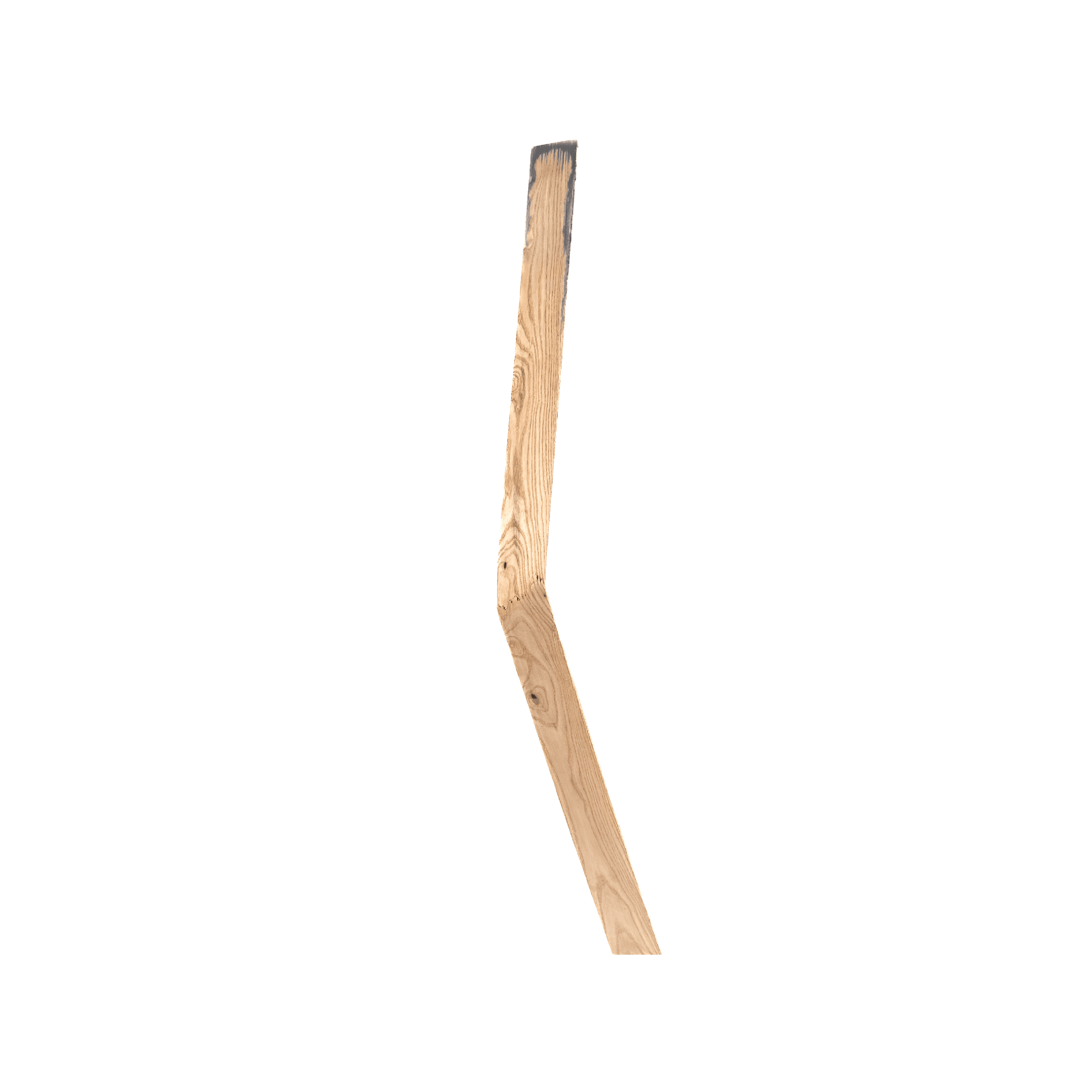
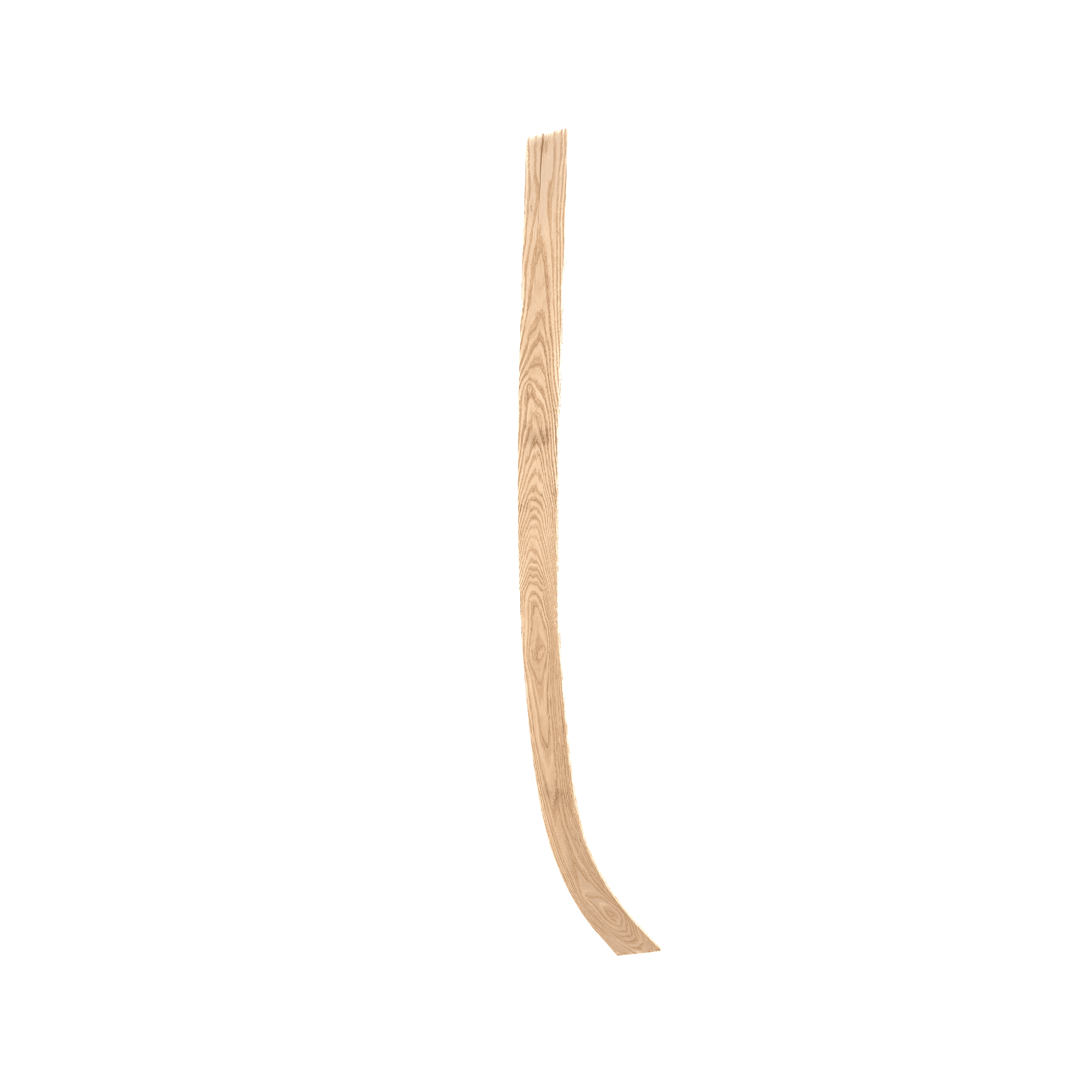
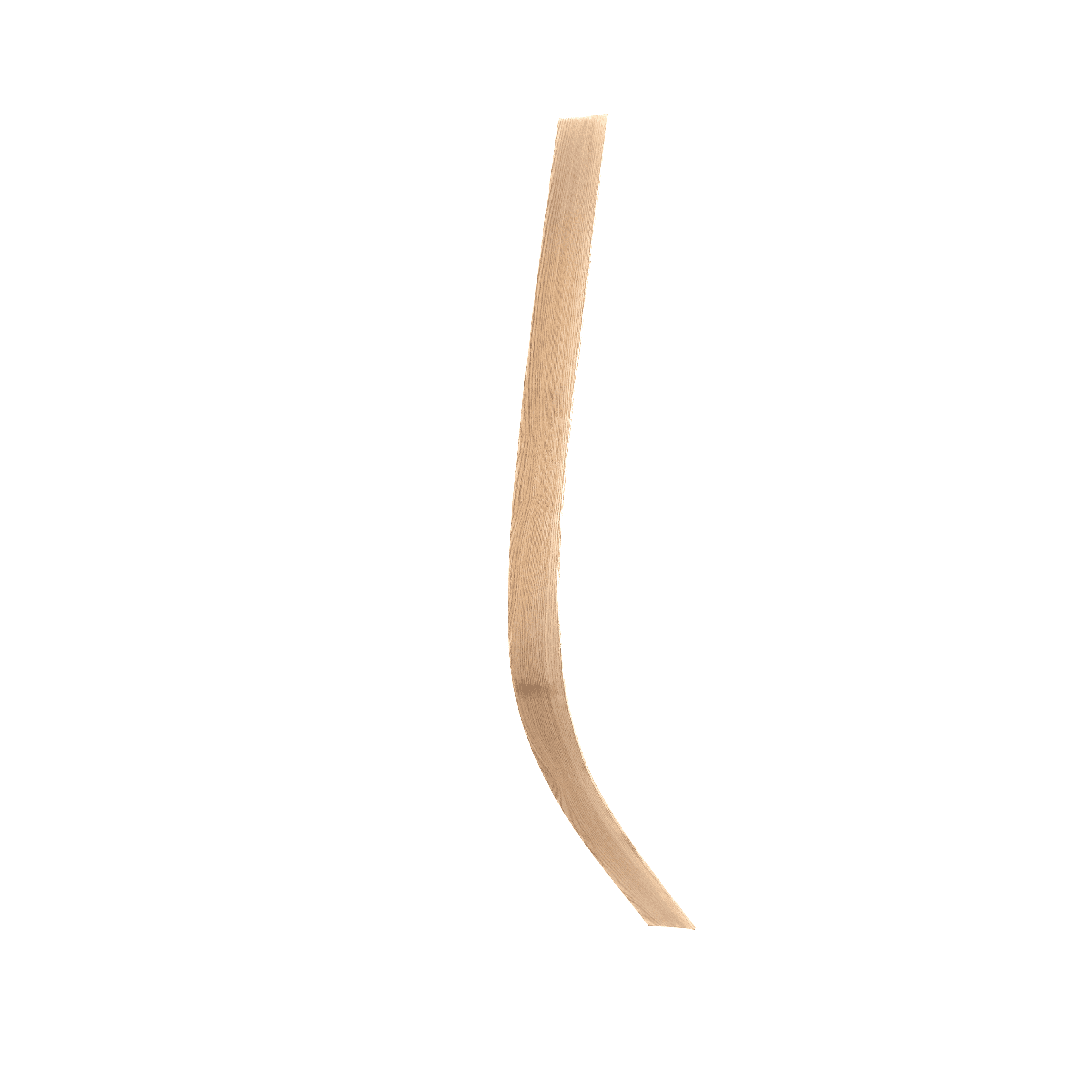
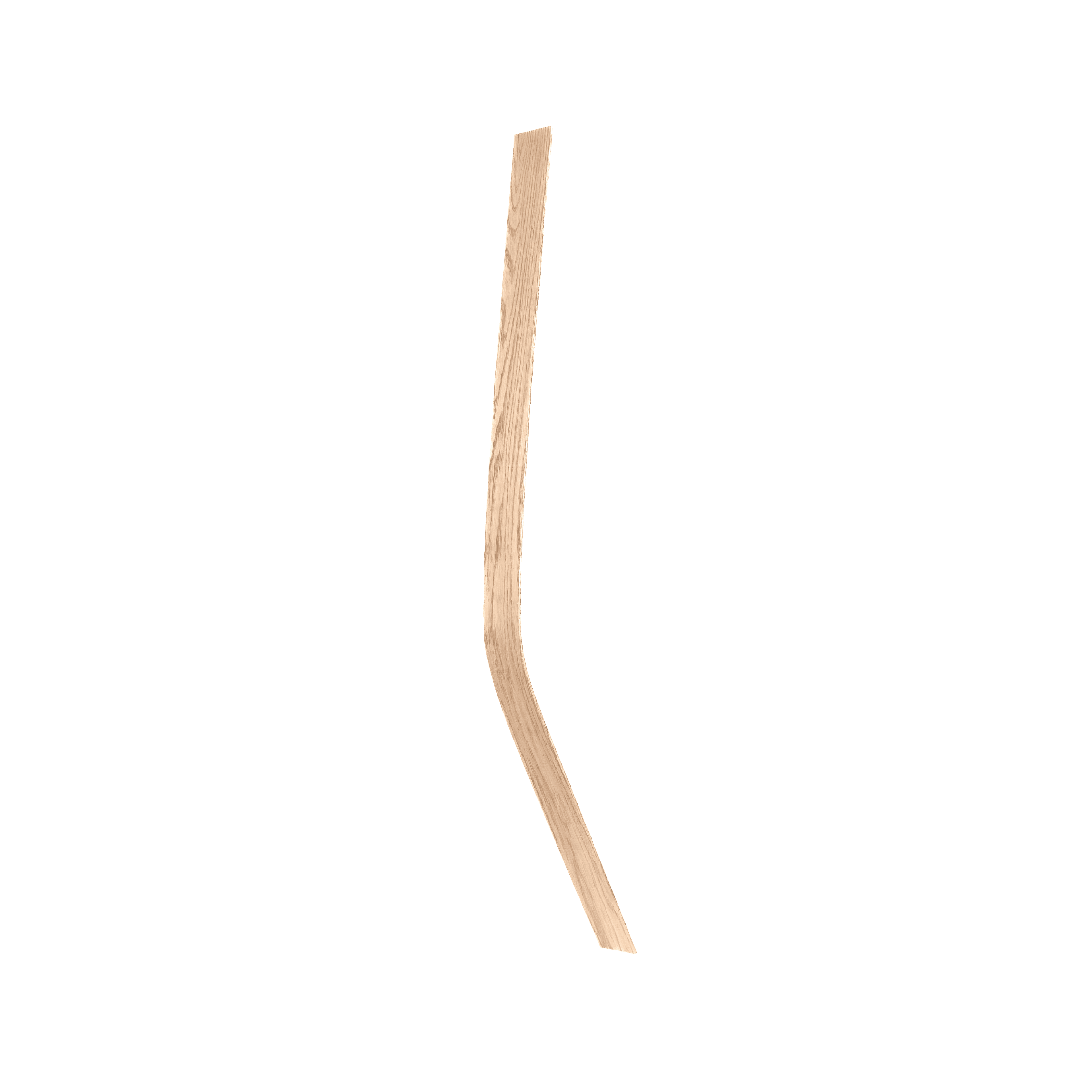
Three target bending conditions were fabricated three times each to establish a controlled comparative test set.
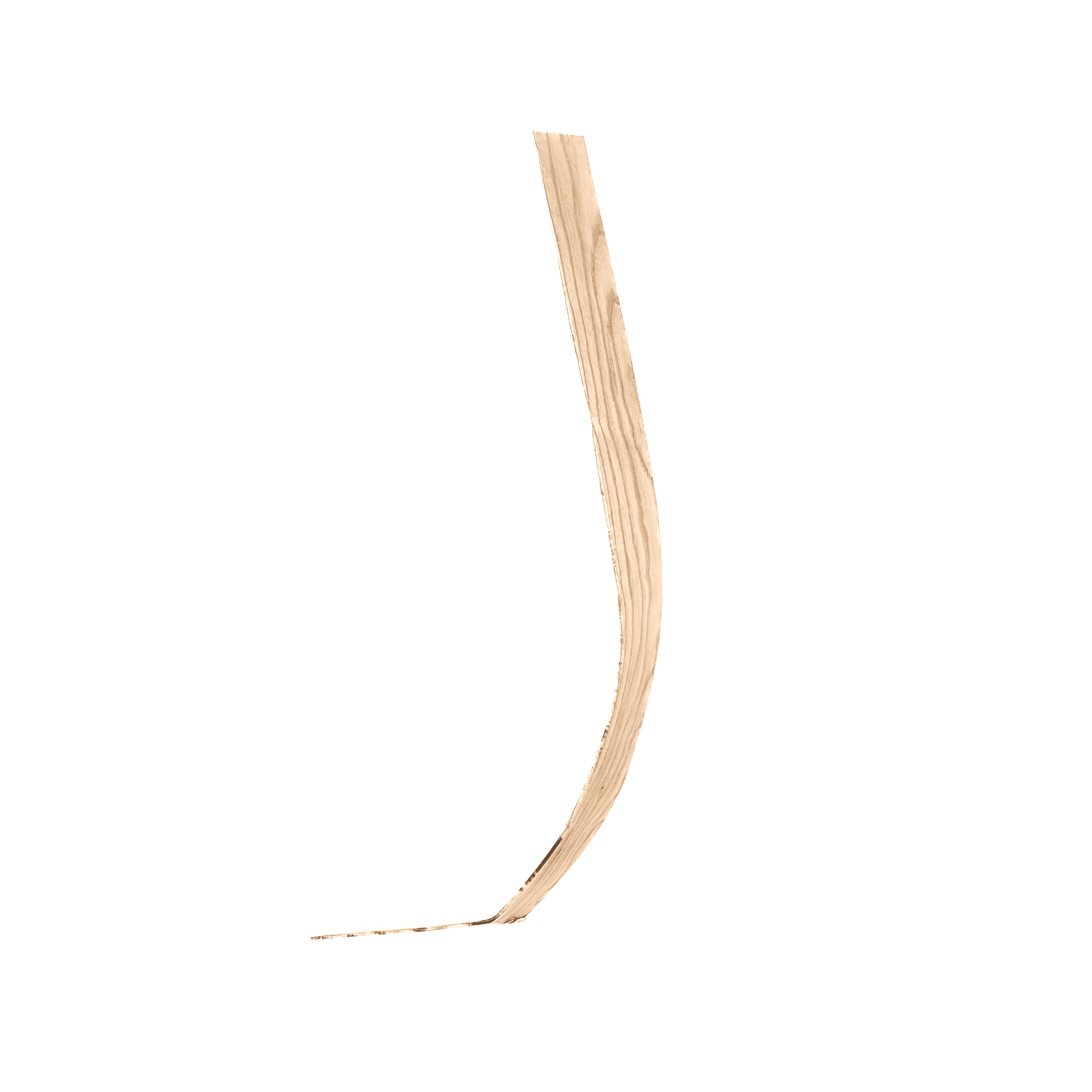
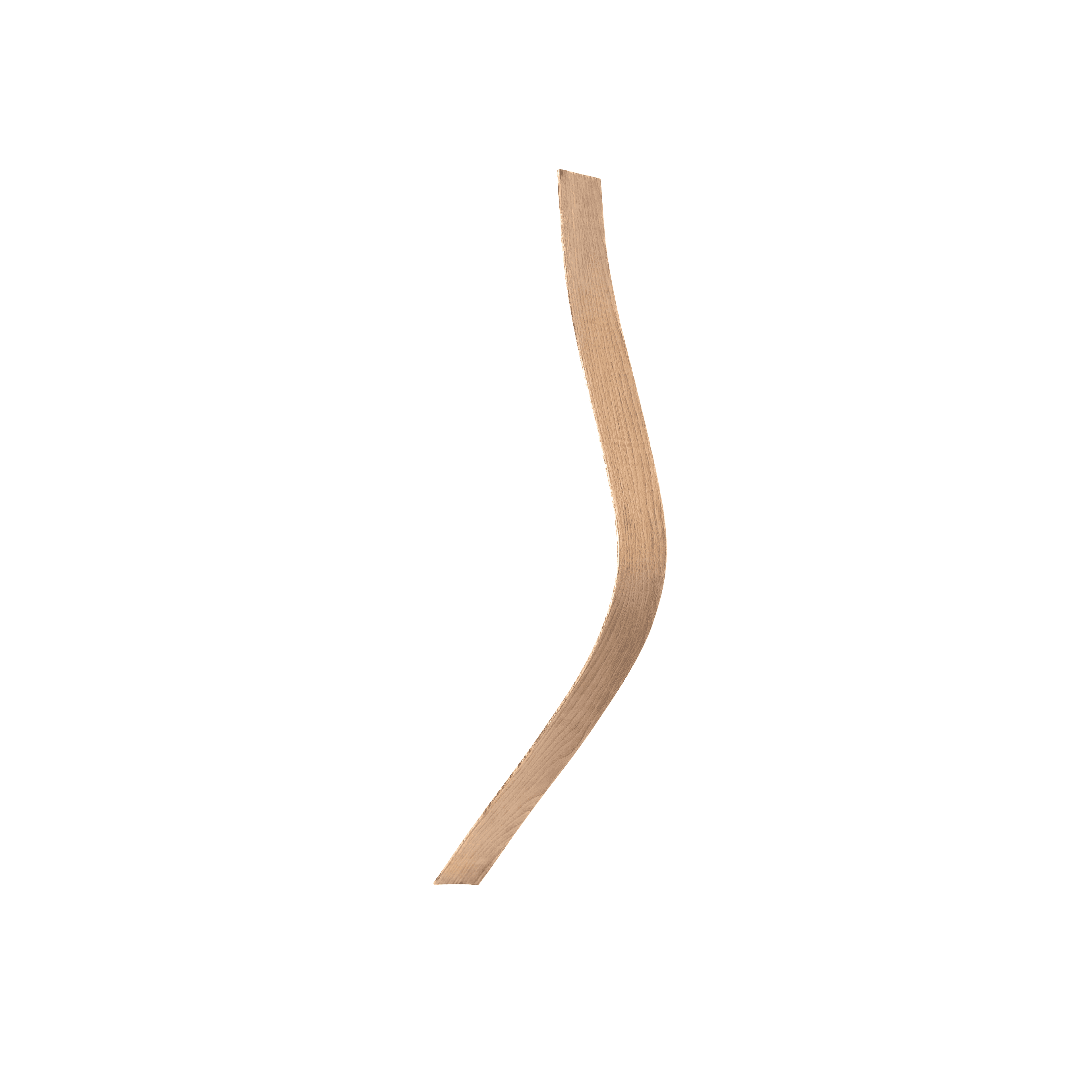
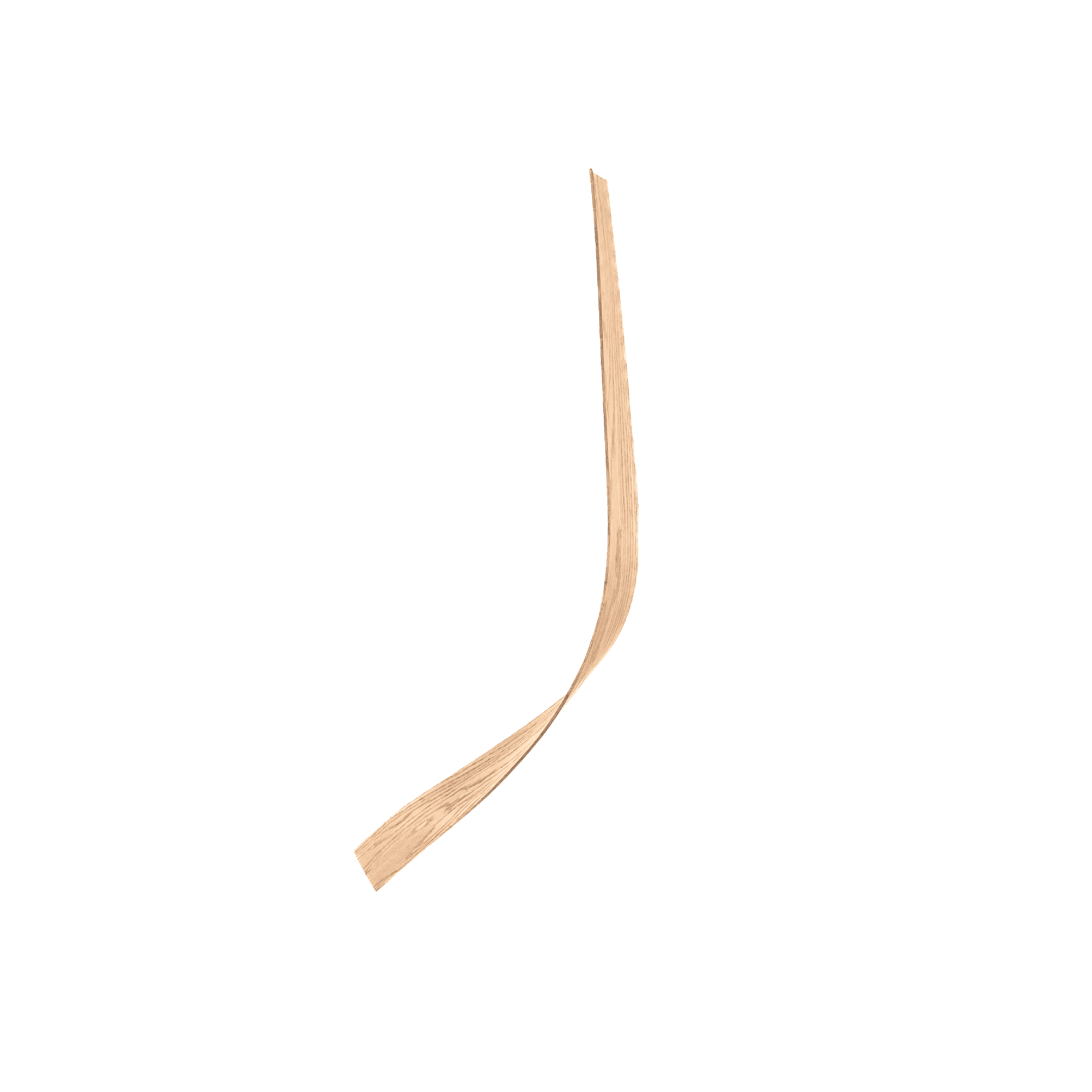
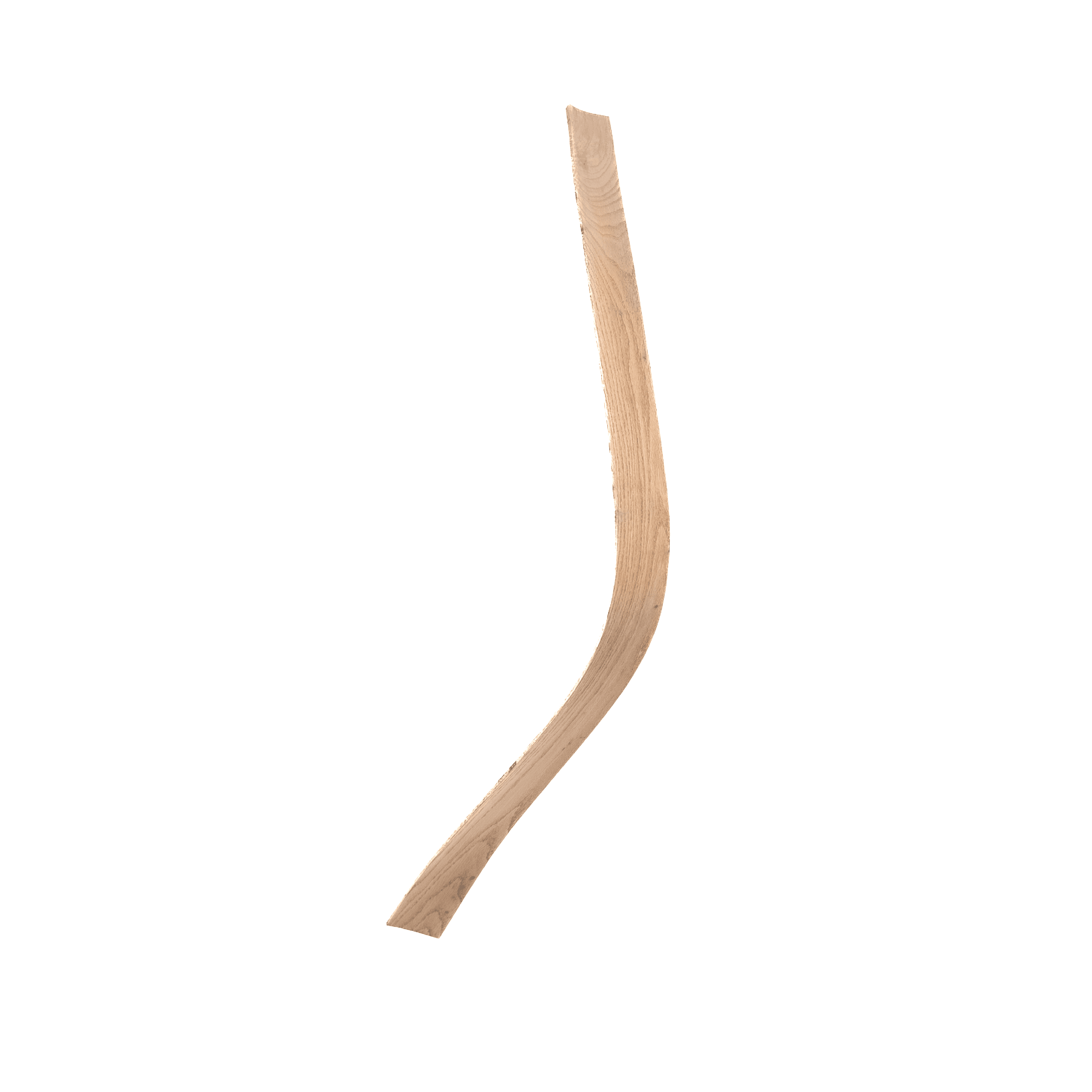
The experiment tested 45°, 75°, and 90° bending conditions, with three independently fabricated specimens produced for each geometry.
Centerlines were extracted from each re-digitized specimen so geometric differences could be compared consistently along the length of each member.
Bend Conditions
45° · 75° · 90°
Repetitions
3 per condition
07
Measuring
Material Change
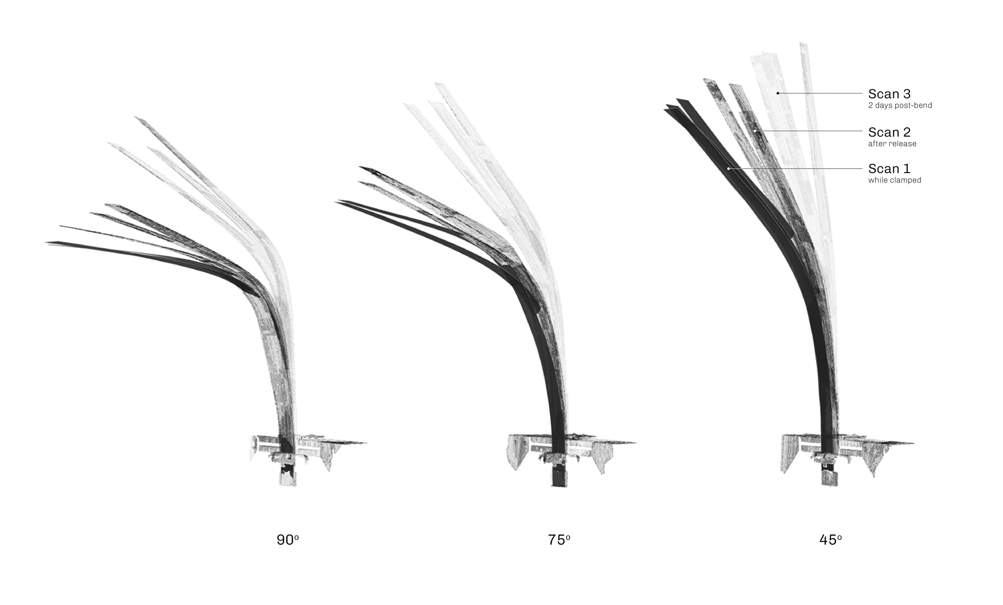
Comparing the same member across three scan states isolates geometric change produced by release and continued material relaxation.
Each specimen was recorded while constrained, after release, and again two days post-bend. Overlaying these states makes the progression of springback visible across the three bending conditions.
08
Springback +
Material Behaviour
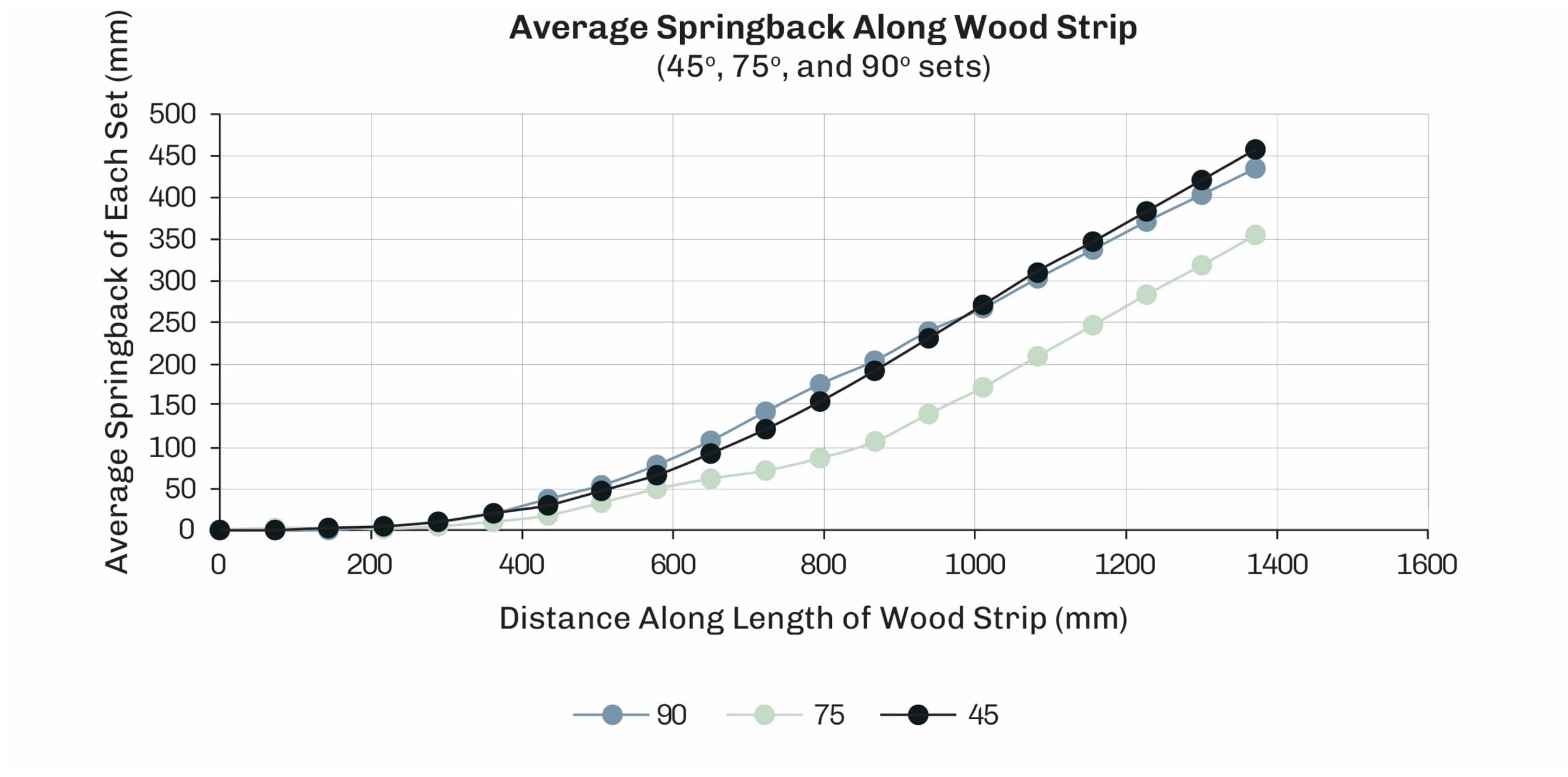
Springback becomes measurable material data rather than an unpredictable fabrication error.
Measuring displacement along each member reveals where geometric change accumulates after release. Material response can therefore be compared spatially across the 45°, 75°, and 90° bending conditions.
09
Accuracy +
Repeatability
The fabricated curves were compared both against each other and against their intended target geometry.
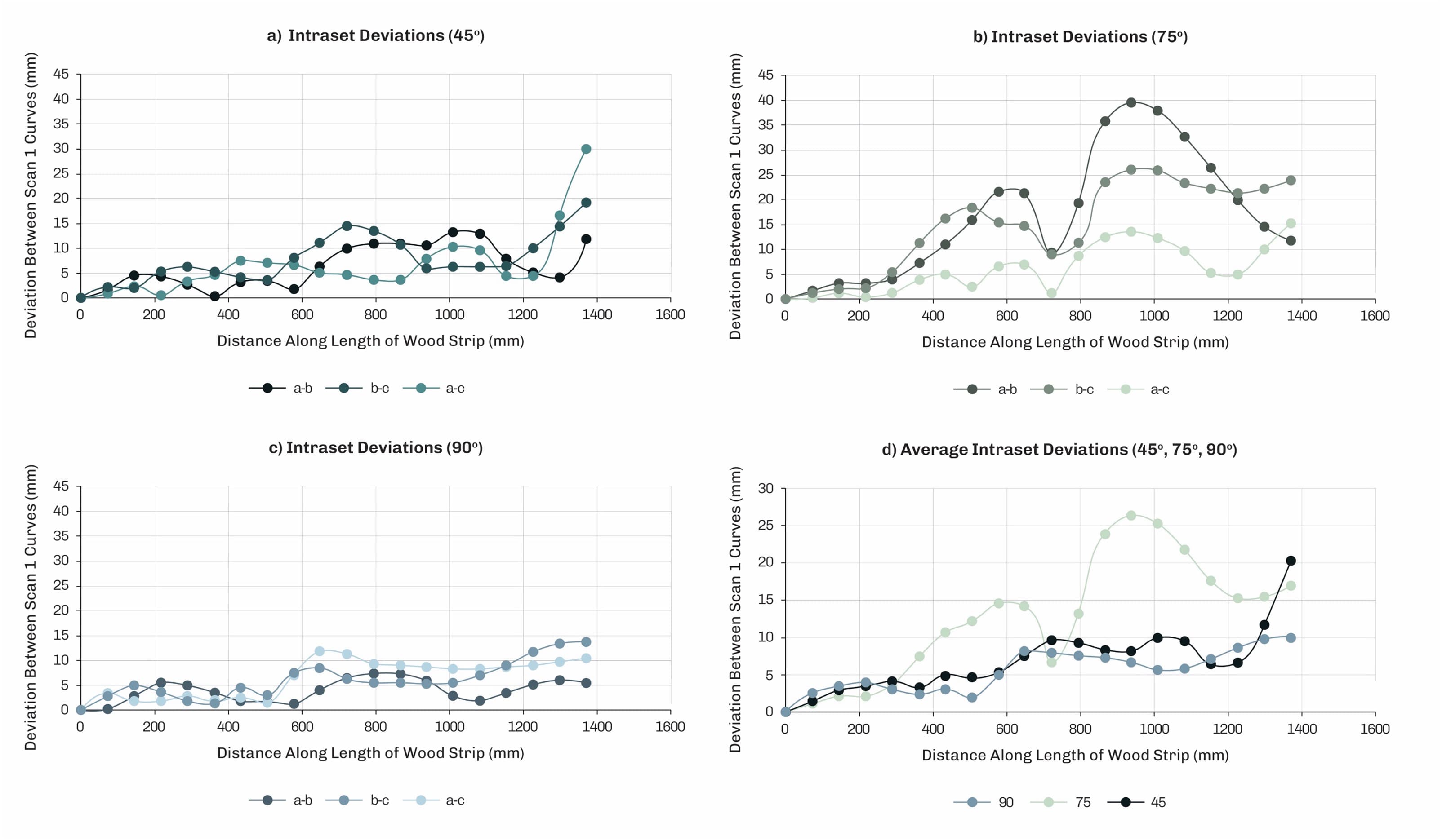
Intraset deviation compares repeated specimens within each bending condition to quantify fabrication repeatability.
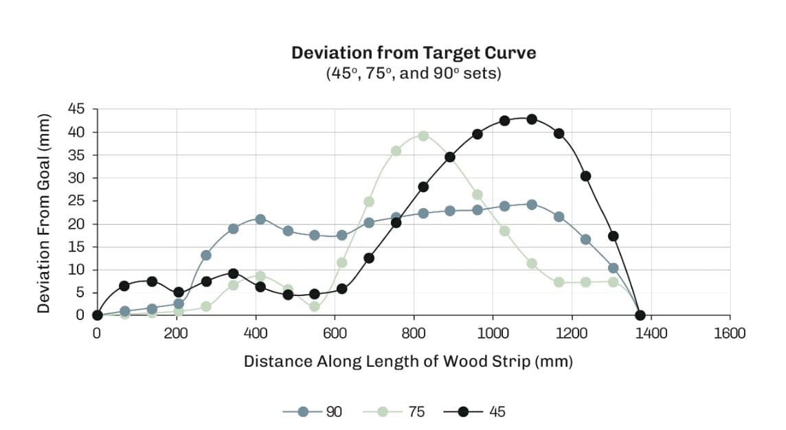
Target deviation measures the difference between the fabricated geometry and the intended computational curve.
≈0 mm
Maximum measured deviation from the target curve for the 45° bending condition.
≈0 mm
Maximum measured deviation from the target curve for the 75° bending condition.
≈0 mm
Maximum measured deviation from the target curve for the 90° bending condition.
0 × 0
Three target bending conditions with three repeated fabrication trials per condition.
10
Material Feedback
→ Assembly
Measured material behaviour becomes feedback for future fabrication, connecting empirical bending data to the design and production of differentiated architectural assemblies.
Rather than treating material variation only as fabrication error, the workflow establishes a basis for incorporating measured physical response into subsequent computational and robotic decisions.

Designing with material variability, rather than against it.
View more projects→Related Side
Projects
Robotic Bending Gripper
Custom end-of-arm tooling for controlled steam bending
Wood Steamer Cart
Mobile steam chamber developed for material preparation and bending experiments
Compression Strap
Custom restraint system for reducing tensile failure during bending
Robotic Heat Gun Tool
End-effector for controlled flash drying