Site under construction — check back daily for updates
Robotic Tooling
Robotic Bending Gripper
A custom robotic end-effector developed to constrain, manipulate, and control timber during formwork-free robotic steam bending.
Type
Robotic End-Effector
Robot
KUKA KR150
Application
Steam Bending
Control
KUKA|prc / Omron PLC
Fabrication
SLS Nylon 3D Printing
CNC Milling
Waterjet Cutting
01
Tool Assembly
The gripper combines a set of mechanical components into a single robotic tool designed around the constraints of steam-bent timber.
Scroll through the exploded assembly to reveal the relationship between the tool body, gripping components, actuation system, and interfaces connecting the gripper to the robot.
02
Design Problem
The tool needed to hold steamed timber securely while still allowing the material to bend, rotate, and respond naturally during robotic manipulation.
Unlike conventional rigid fixturing, the end-effector needed to transfer force into the timber without completely constraining its material response. This required balancing grip strength, contact geometry, clearance, and freedom of movement.
The gripper was therefore developed alongside the larger fabrication workflow, with the tool geometry responding to both the robotic bending path and the physical behaviour observed during steam-bending tests.
03
Clamping + Force Distribution
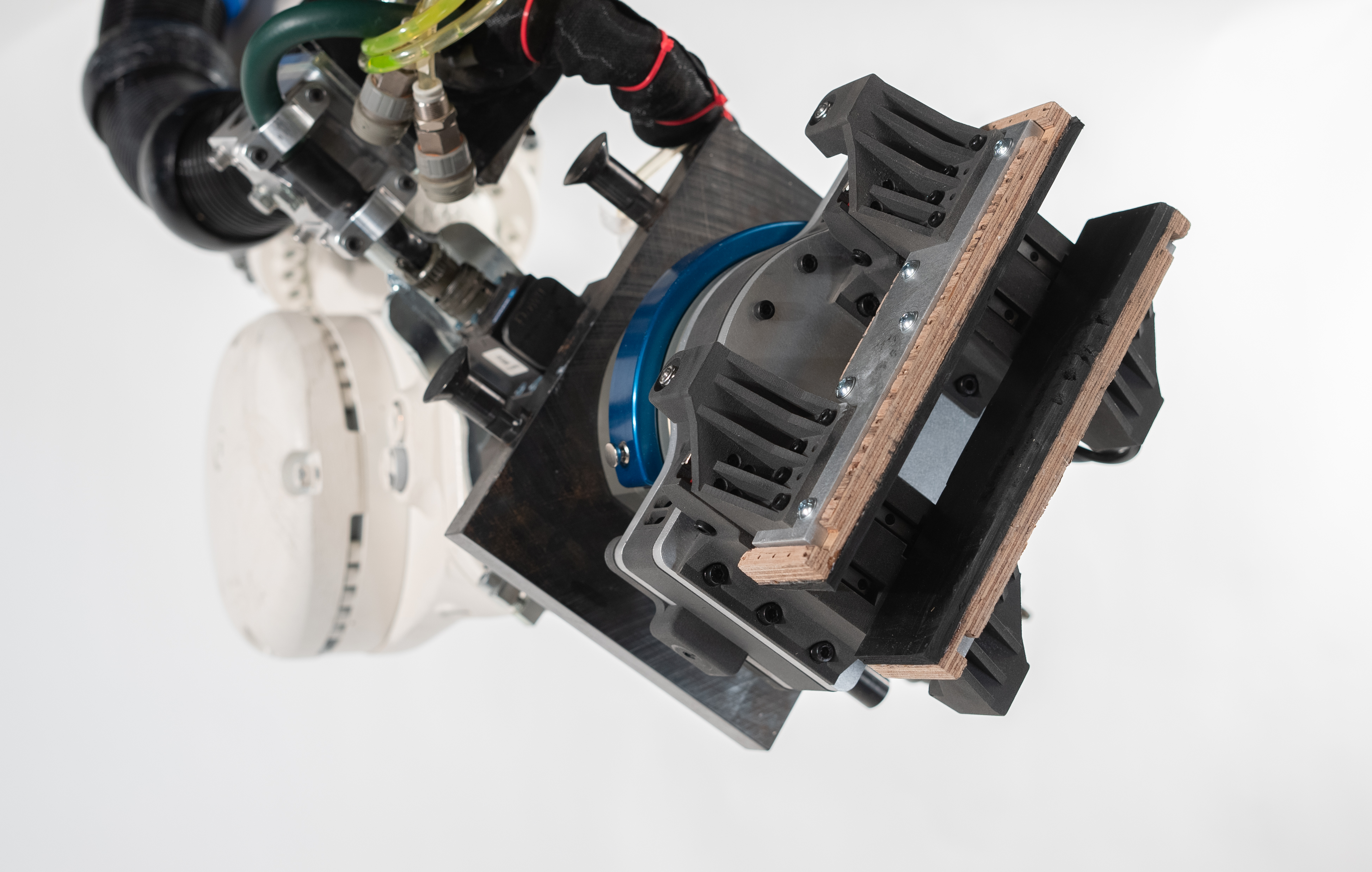
The gripper was designed around the flat face of the timber, maximizing contact area while maintaining a secure connection throughout bending.
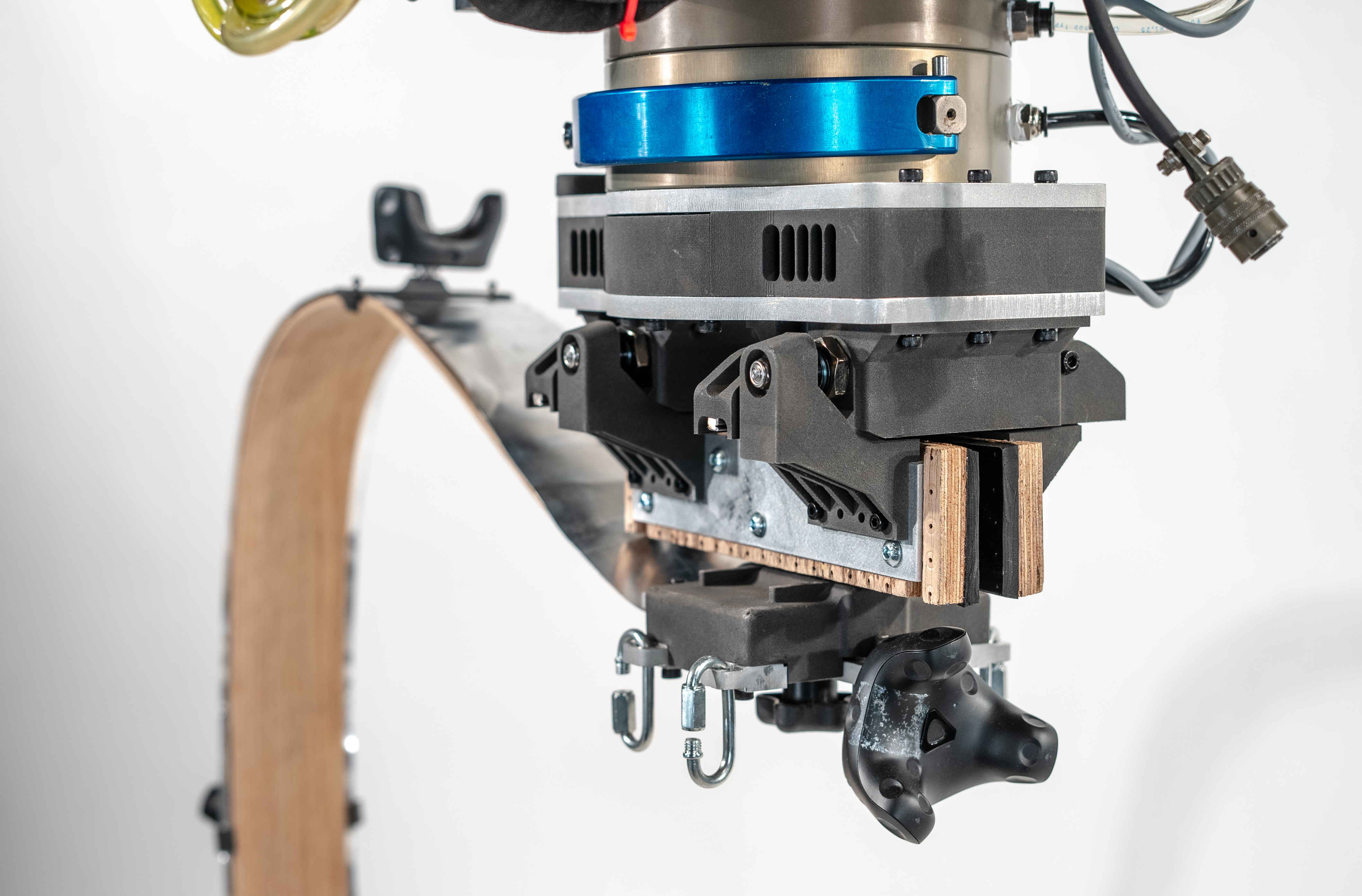
The clamping surface was constructed as a three-part assembly. A milled aluminum plate formed the structural connection to the gripper, a CNC-milled marine plywood plate extended the clamping surface along the timber, and a rubber layer created the final interface with the wood.
Each material performed a specific role within the assembly: aluminum provided rigidity, marine plywood created a lightweight and replaceable contact plate, and rubber increased friction while accommodating small variations in the timber surface. Together, the system could securely grip the steamed wood without relying on highly concentrated clamping forces.
04
Motion + Actuation
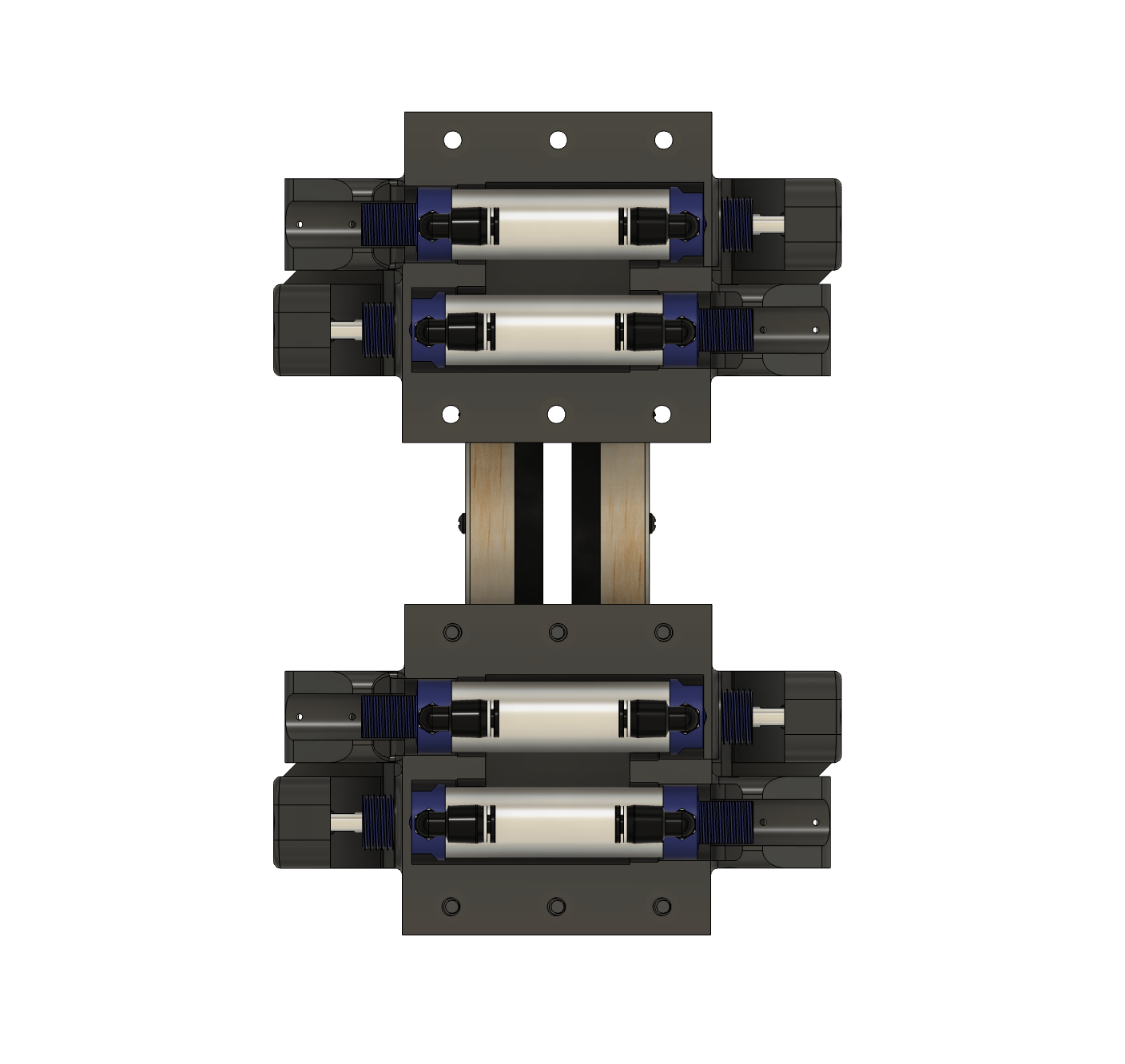
Pneumatic actuation was selected to create a compact parallel gripping system capable of applying controlled clamping force across the extended contact surface.
Each gripper assembly combines two pneumatic cylinders with two linear rails. The cylinders provide the linear actuation required to open and close the gripping mechanism, while their arrangement allows the hardware to remain compact around the central tool body.
The linear rails independently guide the moving assemblies, constraining their motion to a single axis and maintaining alignment throughout the stroke. This separates guidance from actuation so the cylinders primarily provide clamping force rather than resisting lateral loads.
05
Pneumatic Control + PLC Integration
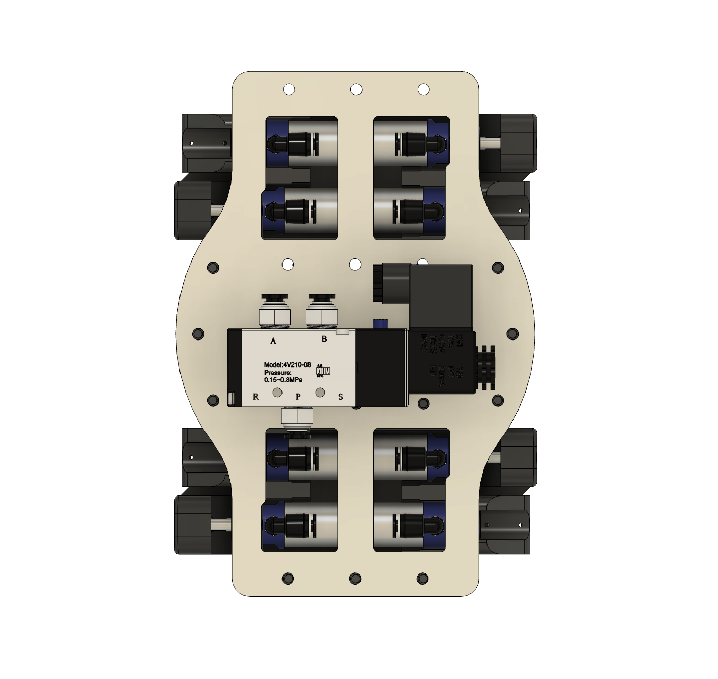
Pneumatic actuation was integrated into the robotic workflow through a 24 V bidirectional solenoid valve controlled directly by the PLC.
The solenoid controls the direction of compressed air supplied to the pneumatic cylinders, switching between extension and retraction to open and close the gripper. This provides a direct electrical interface between the pneumatic system and the digital control architecture.
Connecting the valve to the PLC allowed each gripping action to be coordinated with the robotic bending sequence. The gripper could therefore open, close, and release at defined stages of the automated fabrication workflow.
06
Tool Body + Fabrication
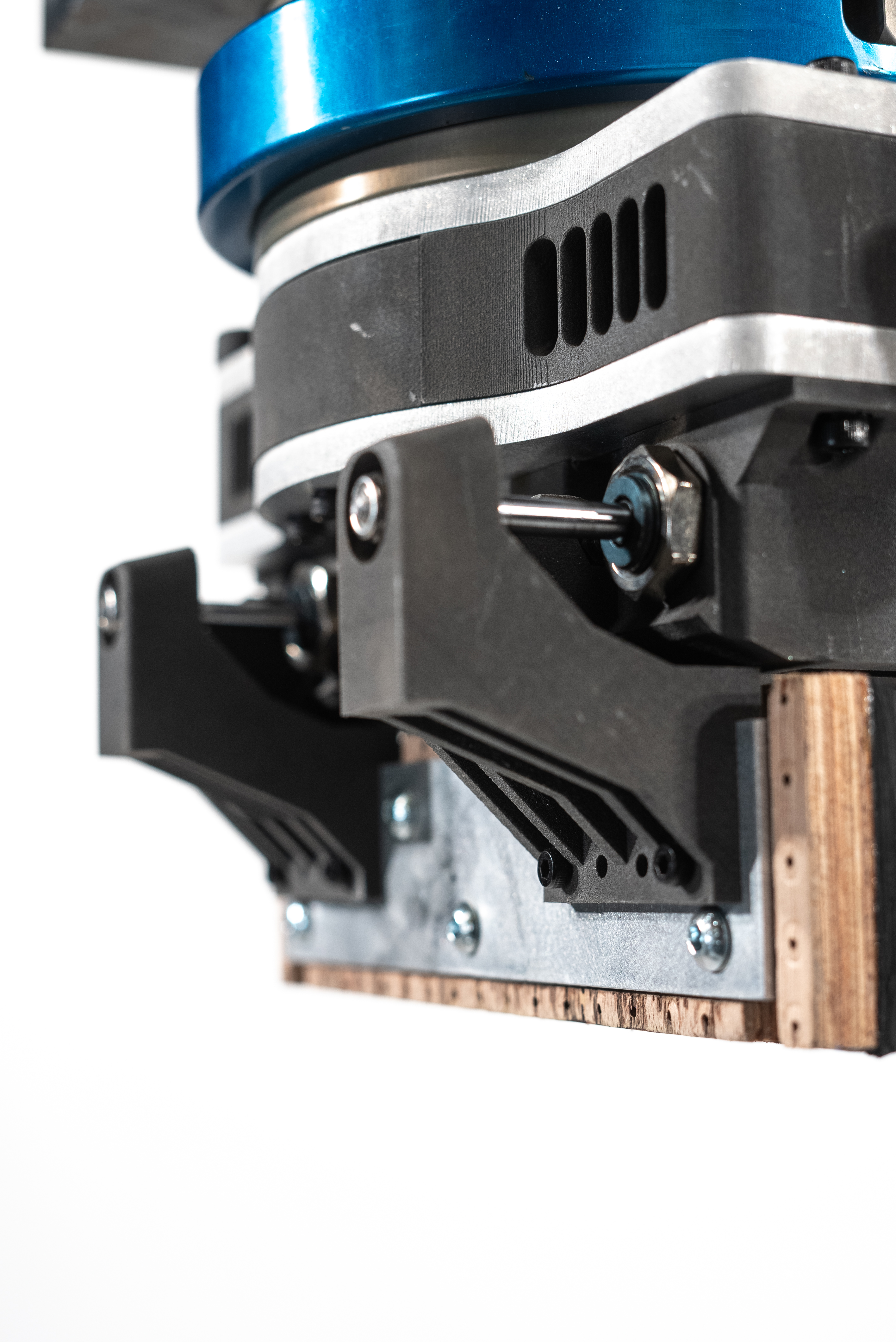
The tool combines custom SLS-printed nylon components with waterjet-cut aluminum plates to create a compact structural assembly around the pneumatic mechanism.
The custom gripper bodies and spacers were fabricated on a FUSE+ SLS printer using nylon powder. Designing these components specifically around the cylinders, linear rails, pneumatic fittings, and mounting hardware allowed the mechanical systems to be packaged directly into the geometry of the tool.
The aluminum top and bottom plates were waterjet cut, then hand-finished, chamfered, and tapped. These plates create the structural interface between the gripper assemblies and the robot's quick-change plate while also locating and securing the remaining components of the gripper.
07
Workflow Adaptation + Compression Strap
As the steam-bending workflow developed, the introduction of a compression strap changed how the timber needed to be held and required the gripper to adapt around the new assembly.
The compression strap was introduced to support the timber during bending and reduce material failure. This added a new physical layer around the workpiece, meaning the gripper could no longer interact with the timber in the same way as the original configuration.
The final gripper configuration was therefore designed to grip the assembly at the centre of the compression strap. This maintained a stable connection to the workpiece while allowing the strap and timber to function together as a single bending assembly throughout robotic manipulation.
View Compression Strap ↗Main Research Project