Site under construction — check back daily for updates
Robotic Fabrication + Assembly
Robotic Wire Tying for Discrete Assembly
Development and evaluation of a sensor-integrated robotic wire-tying system for automated connection-making.
Type
Robotics +
Fabrication
System
Multi-Robot
Assembly
Process
Wire
Tying
Analysis
Process
Sensing
Project
Independent
Acknowledgements
Nicholas Hoban · Zachary Mollica · Rahul Sejpal · Brady Peters · Brian Slocum · Paul Kozak · Anna Geng
Type
Robotics +
Fabrication Research
System
Multi-Robot
Assembly
Process
Wire Tying
Connection Testing
Analysis
Process Sensing
Geometric Deviation
Project
Independent
Research
Acknowledgements
Nicholas Hoban
Zachary Mollica
Rahul Sejpal
Brady Peters
Brian Slocum
Paul Kozak
Anna Geng
01
Research Context
The research investigates how robotic assembly can move beyond positioning components by integrating connection-making as an active and measurable fabrication process.
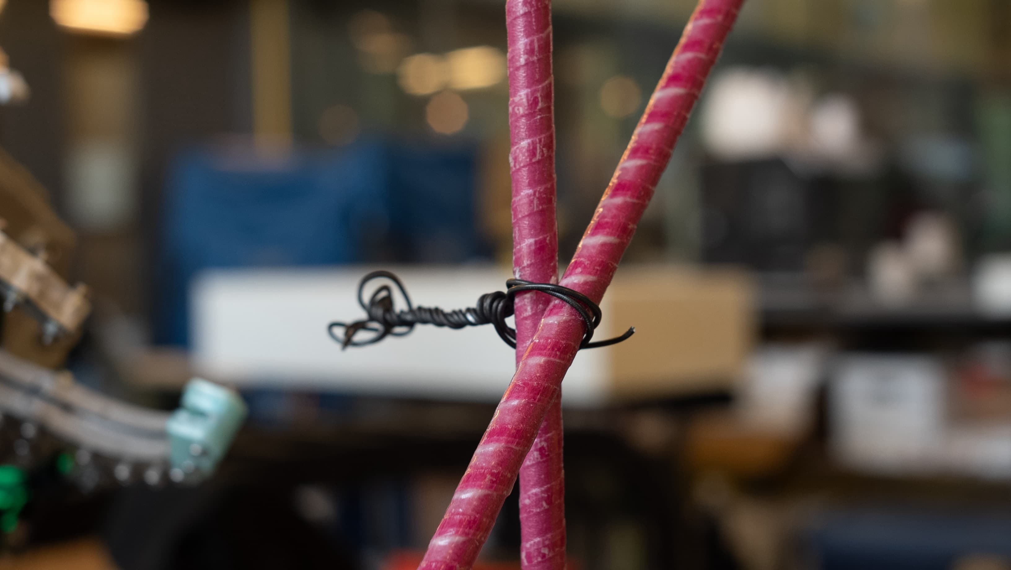
Wire tying provides a lightweight connection method capable of joining discrete members without requiring standardized mechanical fasteners or permanent welded connections. Existing manual and automated systems demonstrate the ability to form these ties efficiently.
Existing robotic systems primarily focus on locating and making the tie. This research instead asks how the connection itself can be evaluated, how fabrication parameters influence its performance, and how sensing can provide feedback during the tying process.
02
Connection Testing
Manual testing established the relationship between tie configuration, twist count, and connection performance prior to robotic implementation.
Single Tie
Baseline Connection Performance
Single-tie specimens were tested to establish a baseline for connection performance. Twist count was varied from two to seven rotations, with peak load and stiffness recorded for each condition.
Performance increased up to approximately five rotations. Beyond this point, continued twisting began to damage the wire and reduced connection strength, defining the initial fabrication range carried forward into robotic testing.
Tap to enlarge
Double Tie
Increased Connection Capacity
Testing was repeated using two ties positioned 90° from one another. The double-tie configuration produced a higher peak load than the single tie, with performance again increasing up to approximately five rotations per tie.
Additional twisting beyond five rotations produced visible wire damage and a reduction in connection strength. The double tie therefore provided the strongest and most robust configuration within the tested range.
Tap to enlarge
Selected Configuration
Double Tie
5 + 5 Rotations
The double tie with five rotations per tie was selected for robotic implementation, reaching a peak load of approximately 2.11 kN while providing greater deformation and energy absorption before failure.
The second tie introduces redundancy into the connection, increasing robustness relative to the single-tie configuration.
Peak Load
~2.11
kN
Energy
~10.7
J
Failure Disp.
~7.3
mm
03
Connection-Making Workflow
The manual tying process was decomposed into four discrete operations that defined the functional requirements of the robotic end effector.
Each operation was translated into a controlled mechanical action, allowing the manual connection sequence to be reproduced through a dedicated robotic tool.
01
Feed Wire
Deliver wire around the connection geometry.
02
Grip
Capture and retain the wire ends.
03
Twist
Rotate the wire to form and tighten the tie.
04
Cut
Separate the completed tie from the wire supply.
Manual Process
Hand Tying
Robotic Process
Automated Tying
04
Robotic Tying Tool
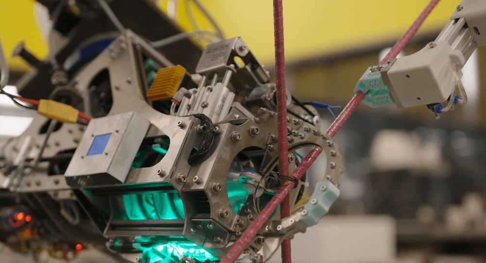
A custom end effector integrates wire feeding, gripping, twisting, and cutting into a single robotic connection-making system.
The tool translates the sequence established through manual tying into a coordinated set of mechanical operations. Wire is delivered around the connection, retained by the gripping mechanism, twisted to form the tie, and cut once the connection is complete.
Integrating these operations within one end effector allows connection-making to become part of the robotic fabrication sequence rather than a separate manual operation.
End Effector
Robotic Wire Tying
05
Process Sensing
Torque sensing was integrated into the end effector to make the mechanical state of the connection visible during the tying process.
A torque sensor positioned within the tying mechanism measures resistance as the wire is progressively tightened. The signal is sampled during rotation and converted into a live torque value that can be monitored while the connection is being formed.
This adds process-level feedback to an operation that would otherwise be defined only by a fixed number of rotations. The current implementation provides a live readout for observing connection behaviour and establishes the sensing architecture for future closed-loop control.
Live Feedback
Torque Readout During Tying
06
Robotic Connection Testing
Robotically produced ties were mechanically tested to determine the fabrication parameters required to reproduce the connection performance established through manual tying.
Robotic Tying
Connection Performance
Peak load continued to increase through eight rotations, with the highest robotic connection strength recorded at this condition.
Stiffness became less consistent at eight rotations, including a sharp reduction in one specimen. Eight rotations therefore represents the strongest tested robotic condition while approaching the upper end of the useful formation range.
Tap to enlarge
Selected Robotic Parameter
8 Rotations
Eight rotations were carried forward for subsequent robotic assembly testing because this condition produced the highest measured peak load within the tested robotic range.
The stiffness response indicates that this condition approaches the upper end of the useful formation range. The parameter was therefore selected on the basis of peak strength while recognizing increasing variability in connection behaviour.
Tested Range
5–8
rotations
Selected
8
rotations
Comparison
Manual vs. Robotic
Both processes followed the same overall trend, but the robotic ties required more rotations to reach comparable peak-load performance.
Manual ties could be tensioned more tightly during initial formation, while the robotic process generated a wider loop that progressively tightened with additional rotation. By eight rotations, robotic peak-load performance approached the strongest manual ties.
Manual Tying
Robotic Tying
07
Multi-Robot Workspace
The validated tying process was integrated into a coordinated multi-robot workspace for member positioning, connection-making, and geometric evaluation.
The assembly workflow distributes tasks between the UR robots and the KUKA system. Members are picked, positioned, and held in relation to the target geometry before the tying robot approaches the connection and executes the fastening sequence.
Component positioning and connection-making operate as dependent stages within a shared robotic workspace, requiring coordinated communication between each robotic system.
System Coordination
PLC-Based Robot Handshake
A Schneider Electric Modicon M221 PLC was integrated into the robotic cell to coordinate communication between the UR robots and the KUKA system. The PLC functions as a central traffic controller, determining when each robot can enter the shared workspace and when the assembly sequence can advance.
Digital I/O handshake signals communicate robot states between each controller and the PLC. Each stage must confirm its state before the next operation is enabled, preventing conflicting robot motions within shared regions and coordinating progression through the assembly sequence.
Full Assembly Process
Coordinated Multi-Robot Assembly
Member Positioning
Rebar Gripper
A separate robotic gripper was developed for the UR10e systems to pick, position, and maintain the fiberglass members during connection-making.
View Rebar Gripper Project↗08
Re-Digitization + Geometric Analysis
Completed assemblies were re-digitized to measure how connection geometry influenced stability after robotic positioning was released.
An Intel RealSense D435 was integrated into the robotic workflow to capture the assembly while the members were held in position and again after release. Multiple scans were transformed into a common coordinate system and merged into a combined point cloud.
Comparing the held and released states allowed geometric movement to be quantified independently from mechanical connection strength. Nearest-neighbour comparison between the merged point clouds was used to calculate deviation.
Robotic Scanning
Multiple scans capture the members, robot tooling, and surrounding workspace. Individual scans are transformed and merged to reconstruct the assembly within a shared reference frame.
Camera Alignment
The camera is mounted to the UR10e and moved through a sequence of scan poses around the assembly center point. The camera plane is transformed relative to the robot TCP so each scan can be reconstructed within the robot coordinate system.
Scan Sequence
Held Geometry to Released Geometry
01
Scan Held
Capture the assembly while robotic positioning maintains the target geometry.
02
Release
Remove robotic constraint and allow the tied assembly to settle.
03
Compare
Re-scan and calculate deviation between held and released geometry.
Test 01
40° · Single Tie
The initial configuration uses a single connection between members positioned at 40°. This assembly experienced the greatest post-release movement of the four tested geometries.
Mean
64.16
mm
P95
136.54
mm
Base Geometry
Before Release
After Release
Geometric Deviation
0≥5 mm
Tap any figure to enlarge
Test 02
50° · Single Tie
Increasing the assembly angle to 50° improved geometric stability while retaining a single-tie connection. Post-release deviation decreased substantially relative to the 40° condition.
Mean
15.93
mm
P95
39.99
mm
Base Geometry
Before Release
After Release
Geometric Deviation
0≥5 mm
Tap any figure to enlarge
Test 03
60° · Crossing Ties
Crossing ties introduced additional constraint at the connection. This reduced post-release movement further, demonstrating the importance of tie arrangement in maintaining assembly geometry.
Mean
7.47
mm
P95
18.20
mm
Base Geometry
Before Release
After Release
Geometric Deviation
0≥5 mm
Tap any figure to enlarge
Test 04
60° · Crossing Ties · Varied Z-Plane
The final condition combined crossing ties with variation in the connection Z-plane. Increasing constraint across multiple orientations produced the most geometrically stable assembly.
Mean
2.14
mm
RMSE
3.02
mm
P95
6.06
mm
Base Geometry
Before Release
After Release
Geometric Deviation
0≥5 mm
Tap any figure to enlarge
Best Performing Geometry
60° Crossing Ties
Varied Z-Plane
Post-release deviation decreased as connection geometry introduced greater constraint. The final crossing-tie configuration reduced mean deviation from 64.16 mm to 2.14 mm.
More importantly, the same measurement workflow establishes a baseline for evaluating future connections. New tie patterns, fastening systems, materials, and connection geometries can be compared using the same sequence of robotic positioning, scanning, release, and geometric deviation analysis.
Mean
2.14
mm
RMSE
3.02
mm
P95
6.06
mm
09
Outlook
The system points toward robotic connection-making as part of a more adaptive architectural fabrication workflow for producing non-standard reinforcement, spatial frameworks, and complex building assemblies.
Rather than treating tying as a repetitive operation applied to standardized cages, robotic positioning and connection control could allow reinforcement to respond directly to changing structural and geometric requirements within a digital model.
On-Demand Reinforcement
Custom Rebar Cages for Non-Standard Geometry
Multi-robot positioning and automated tying could support reinforcement cages generated directly from project-specific geometry rather than relying only on repetitive orthogonal layouts. Member angle, connection location, and tie orientation could vary across the assembly in response to structural and architectural requirements.
Mass Customization
Geometry-Specific Fabrication
Because each connection is computationally defined rather than mechanically fixed by a dedicated jig, the same robotic system could fabricate families of unique assemblies without requiring a new production setup for every geometry. This creates a path toward low-volume or one-off reinforcement systems for geometrically complex buildings.
Robotic Construction
Integration with Additive Construction
A future workflow could coordinate reinforcement assembly with robotic concrete or material extrusion. Reinforcing members could be positioned and tied as a structure is printed, allowing reinforcement geometry and deposited material to develop together rather than treating the cage as a completely separate prefabricated system.
Closed-Loop Fabrication
Connections that Respond to Fabrication
Torque sensing and geometric re-digitization provide two levels of feedback: local information about how the tie is forming and global information about how the assembly moves after release. Combining these measurements could allow future systems to adapt tie parameters, add connections, or modify assembly geometry in response to measured fabrication behaviour.
Architectural Application
From Connection Tool
to Fabrication System
The longer-term opportunity is not simply automating a conventional rebar tie, but using robotic connection-making as a flexible fabrication operation that enables assemblies whose geometry would be difficult to produce through conventional prefabrication.
In this context, the end effector, multi-robot coordination, process sensing, and re-digitization workflow become parts of a larger architectural production system capable of moving continuously between digital geometry, physical assembly, measurement, and corrective fabrication.
The same framework could extend beyond wire tying to other robotic connection methods, creating a common baseline for testing how discrete components are joined, how those connections perform, and how complete assemblies retain their intended geometry.